Tube drawing forming method and forming mould

A technology for pipe drawing and pipe material, applied in methods and forming dies, pipe drawing and forming fields, can solve problems such as cracking, affecting the safety and reliability of aircraft pipelines, insufficient strength, etc., achieve a large degree of deformation, and eliminate internal tissue defects , the effect of changing shape and distribution

Inactive Publication Date: 2013-07-17
NORTHWESTERN POLYTECHNICAL UNIV
View PDF5 Cites 0 Cited by
  • Summary
  • Abstract
  • Description
  • Claims
  • Application Information

AI Technical Summary

Problems solved by technology

A variable-channel extrusion die proposed by Northwestern Polytechnical University in a patent application with a publication number of CN201371172, and a tire mold for long-axis forging blanks proposed in a patent application with a publication number of CN201711480U, and the publication number A device for preparing variable-channel ultra-fine-grained copper-aluminum wires proposed in the patent application of CN201862645U is formed by a variable-section torsional mold cavity that changes from a circular cross-section to an elliptical cross-section, and then from an elliptical cross-section to a circular cross-section. The prefabricated workpiece has the characteristics of simple structure, small load, low cost and high efficiency. It can be widely used in the production of bars and wires of steel and non-ferrous metals, as well as the production of large shaft parts, high-speed steel and powder metallurgy and other hard-to-deform materials. billet, but no one has used this simple subsequent processing method for pipes
[0006] The above-mentioned traditional pipe-making process is difficult to meet the needs of the growing aviation industry. Due to insufficient strength and the influence of deformation texture, cracking will occur during use, which will affect the safety and reliability of aircraft pipelines in severe cases.

Method used


Image

  • Tube drawing forming method and forming mould
  • Tube drawing forming method and forming mould
  • Tube drawing forming method and forming mould

Examples


Embodiment 1

[0041] This embodiment is a method for The drawing method of aluminum tube with a wall thickness of 1mm and a length of 20mm.

[0042] The method for drawing and forming an aluminum tube proposed in this embodiment includes the following steps:

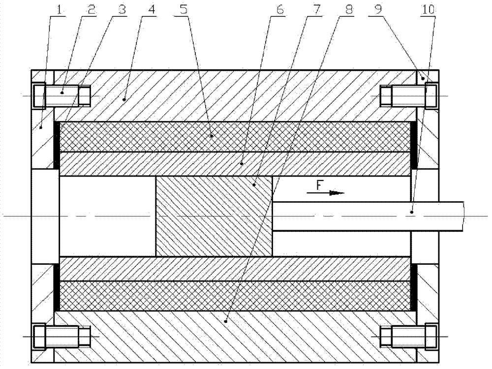
[0043] Step one, install the mold. Coat the inner and outer walls of the pipe 6 with lard lubricant. The tube 6 coated with lubricant is put into the polyurethane filling layer 5. Place the polyurethane filling layer 5 with the tube 6 in the lower mold sleeve 8 and place the gasket 3 at the end faces of the two ends of the polyurethane filling layer 5; the tube 6 and the polyurethane filling layer 5 have the same length. Place the upper mold sleeve 4 on the lower mold sleeve 8 and make the parting surfaces of the upper mold sleeve 4 and the lower mold sleeve 8 tightly buckle, and the two ends of the upper mold sleeve 4 and the lower mold sleeve 8 are aligned. Fix the inlet end cover 1 and the outlet end cover 9 with screws 2 respective...

Embodiment 2

[0048] This embodiment is a method for A method of drawing and forming a copper tube with a wall thickness of 3mm and a length of 30mm.

[0049] The method for drawing and forming a copper tube proposed in this embodiment includes the following steps:

[0050] Step one, install the mold. Coat the inner and outer walls of the pipe 6 with lard lubricant. The tube 6 coated with lubricant is put into the polyurethane filling layer 5. Place the polyurethane filling layer 5 with the tube 6 in the lower mold sleeve 8 and place the gasket 3 at the end faces of the two ends of the polyurethane filling layer 5; the tube 6 and the polyurethane filling layer 5 have the same length. Place the upper mold sleeve 4 on the lower mold sleeve 8 and make the parting surfaces of the upper mold sleeve 4 and the lower mold sleeve 8 tightly buckle, and the two ends of the upper mold sleeve 4 and the lower mold sleeve 8 are aligned. Fix the inlet end cover 1 and the outlet end cover 9 with screws 2 res...

Embodiment 3

[0055] This embodiment is a method for Variable cross-section drawing forming method for steel pipes with a wall thickness of 5mm and a length of 50mm.

[0056] The method for drawing and forming a steel pipe proposed in this embodiment includes the following steps:

[0057] Step one, install the mold. Coat the inner and outer walls of the pipe 6 with lard lubricant. The tube 6 coated with lubricant is put into the polyurethane filling layer 5. Place the polyurethane filling layer 5 with the tube 6 in the lower mold sleeve 8 and place the gasket 3 at the end faces of the two ends of the polyurethane filling layer 5; the tube 6 and the polyurethane filling layer 5 have the same length. Place the upper mold sleeve 4 on the lower mold sleeve 8 and make the parting surfaces of the upper mold sleeve 4 and the lower mold sleeve 8 tightly buckle, and the two ends of the upper mold sleeve 4 and the lower mold sleeve 8 are aligned. Fix the inlet end cover 1 and the outlet end cover 9 wi...


PUM

PropertyMeasurementUnit
lengthaaaaaaaaaa
thicknessaaaaaaaaaa
lengthaaaaaaaaaa

Abstract

The invention discloses a tube drawing forming method and forming mould. In the forming method, extrusion-bulging deformation is performed on a tube by using a drawing torsion variable-section core to realize combination of various deformation modes in a primary forming process. The tube wall of the formed tube is subjected to the extrusion-bulging of the core and is in a strong three-way compressive stress state due to the limitation of a polyurethane filling layer; at a deformation stage of circular-elliptical-circular and elliptical torsion change, the tube enters a torsion shearing deformation zone of a metal transition region; under the action of shearing stress, the internal organization of the material is subjected to rotation and shear strain to cause the orientation of a materialorganization structure, namely a new texture is formed, thereby improving deformation texture under the equivalent deformation degree. The drawing variable-section core extrusion-bulging tube deformsto achieve larger deformation degree compared with that of the conventional forming process, so that strain distribution and stress distribution in the tube are improved, the casting organization remained in the broken tube is facilitated, the form and the distribution of inclusion are changed, and the defects of the internal organization of the tube are overcome.

Description

Technical field [0001] The invention relates to the forming field of metal pipes such as aluminum, copper, steel, etc., in particular to a method and a forming die for drawing and forming pipes. Background technique [0002] In the fields of aviation, aerospace, automobile and machinery equipment, all involve the use of pipe fittings and pipe sleeves. Take an airplane as an example. The pipeline system is the lifeline of the airplane. Its performance directly affects the overall performance of the airplane. If the engine is compared to the heart of the airplane, the pipeline is like the blood vessel of the airplane. Therefore, improving the technical level of the pipeline system is very important for improving the performance of the aircraft. [0003] At present, the metal pipes used in piping systems on the market mostly adopt traditional forming methods, and most of them are seamless pipes (Baogang Technology, 2002, 2:21). The characteristic of this kind of pipe is that the thi...

Claims


Application Information

Patent Timeline
Patent Type & Authority Patents(China)
IPC IPC(8): B21C1/24B21C3/02
Inventor 薛凤梅李付国汪程鹏袁战伟
Owner NORTHWESTERN POLYTECHNICAL UNIV
Why Eureka
Try Eureka