Blast furnace gas washing deacidification apparatus and method thereof

A technology of blast furnace gas and coal gas, which is applied in combustible gas purification, combustible gas purification/transformation, petroleum industry, etc., and can solve the problems of abnormal operation of pressure reducing valves and other components, safety hazards of blast furnace gas and gas pipelines, and cavitation and cracking of compensators, etc. problem, to achieve the effects of small footprint, small heat loss, and prevention of electrochemical corrosion

Inactive Publication Date: 2012-04-25
秦皇岛双轮环保科技股份有限公司
View PDF12 Cites 3 Cited by
  • Summary
  • Abstract
  • Description
  • Claims
  • Application Information

AI Technical Summary

Problems solved by technology

The corrosion of blast furnace gas is mainly due to the electrochemical corrosion of salt precipitated in the condensed water in the pipeline, which is mainly manifested in the frequent cavitation and cracking of the compensator, gas leakage on the

Method used


Image

  • Blast furnace gas washing deacidification apparatus and method thereof
  • Blast furnace gas washing deacidification apparatus and method thereof

Examples


Embodiment 1

[0025] Example 1 Equipment

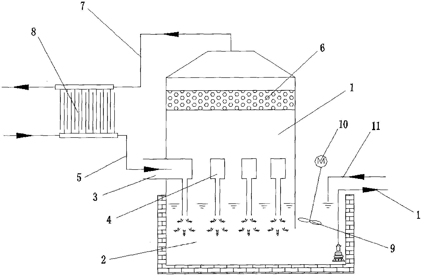
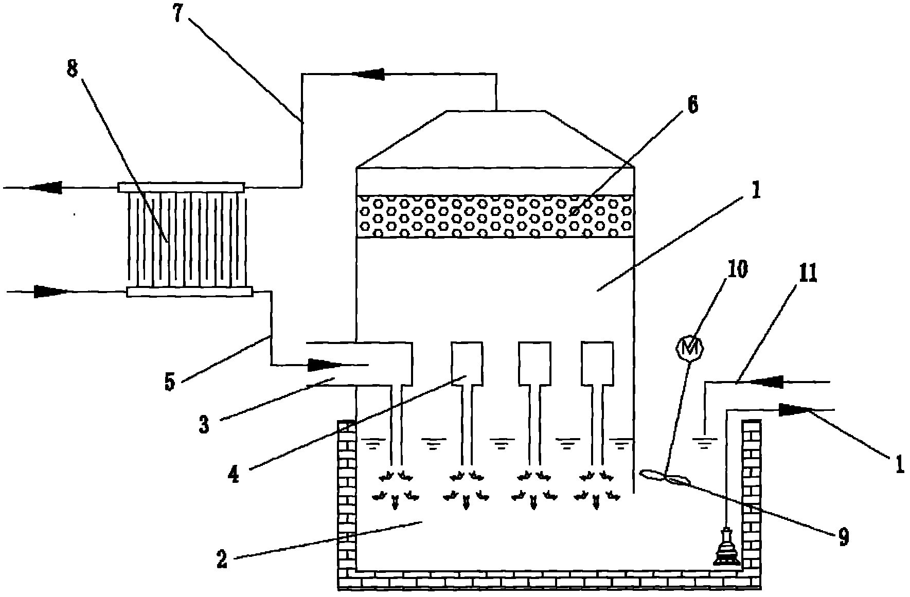
[0026] Such as figure 1 As shown, the present invention provides a blast furnace gas scrubbing and deacidification equipment, comprising a scrubber 1 and an absorption liquid storage tank 2, the middle part of the scrubber is provided with an air inlet pipeline 3 and a plurality of gas dispersion pipelines 4, the inlet The gas pipeline is connected to the original gas pipeline 5 and communicated with multiple gas dispersion pipelines. The bottom of the washing tower is connected to the absorption liquid storage pool, and the bottom of the gas dispersion pipeline extends into the absorption liquid storage pool. The upper part of the washing tower is set There is a packing layer 6, and the purified gas pipeline 7 is connected to the top of the washing tower.

[0027] A heat exchange device 8 is arranged between the raw gas pipeline and the purified gas pipeline.

[0028] A stirring device 9 is arranged in the absorption liquid reservoir, and the st...

Embodiment 2

[0030] Example 2 Blast Furnace Gas Washing and Deacidification Method

[0031] The washing method uses the liquid storage tank, the washing tower and the absorption liquid at the bottom of the washing tower. The absorption liquid is sodium chloride with a weight concentration of 20%. After the raw gas passes through TRT, the raw gas temperature is between 100 and 200°. The gas pipeline and multiple gas dispersing pipelines enter the scrubber, and enter the absorption liquid storage pool at the bottom of the scrubber downward at a high flow rate of not less than 20m / s. The gas is dispersed into fine bubbles and evenly dispersed in the absorption liquid. The absorption process It mainly occurs in two areas: the first is the liquid continuous phase area below the liquid surface of the absorption liquid, which is dispersed into fine bubbles and evenly dispersed in the absorption liquid, and the acid gas molecules are absorbed through the gas-liquid film mass transfer; the second is...


PUM


Abstract

The invention discloses a blast furnace gas washing deacidification apparatus and a method thereof. The apparatus is characterized in that: the apparatus comprises a washing tower and an absorption liquid storage pool; the middle part of the washing tower is provided with a gas inlet pipeline and a plurality of gas dispersing pipelines; the gas inlet pipeline which is connected with a raw gas pipeline is communicated with the gas dispersing pipelines; the bottom of the washing tower is communicated with the absorption liquid storage pool; the bottom of each gas dispersing pipeline stretches into the absorption liquid storage pool; the upper part of the washing tower is provided with a packing layer; the top of the washing tower is connected with a purified gas pipeline; a heat exchanging device is arranged between the raw gas pipeline and the purified gas pipeline; a stirring device is arranged in the absorption liquid storage pool; and the stirring device is connected with a stirring motor. The apparatus of the invention allows the salt substance precipitation on pipelines to be reduced and the salt electrochemical corrosion to be eliminated through washing the blast furnace gas.

Description

technical field [0001] The invention relates to blast furnace gas washing and acid removal equipment and a method. Background technique [0002] Blast furnace gas dedusting gradually eliminates wet dedusting and adopts dry dedusting. Due to the lack of water washing, the dry dust removal can preserve the soluble salts and other substances contained in the gas, which has brought certain adverse effects on the subsequent production process and equipment, among which the corrosion of blast furnace gas is one of them. The corrosion of blast furnace gas is mainly due to the electrochemical corrosion of salts precipitated in the condensed water in the pipeline. It is mainly manifested in the frequent cavitation and cracking of the compensator, the gas leakage on the pipeline, and the failure of normal operation of valves and pressure reducing valves on the pipeline due to corrosion. [0003] The corrosiveness of blast furnace gas has brought serious safety hazards to equipment op...

Claims


Application Information

Patent Timeline
IPC IPC(8): C10K1/12
Inventor 姜述玉姚殿宝温建孙艳燕
Owner 秦皇岛双轮环保科技股份有限公司
Why Eureka
Try Eureka