Heavy-type combustion engine high-temperature turbine double-medium cooling blade

A technology for cooling blades and duplexes, which is applied in the cooling of turbines/propulsion devices, cooling of engines, and supporting components of blades, etc., which can solve problems such as low efficiency, uneven distribution, and complex blade structure of gas turbines, and achieve improved Thermal efficiency, enhanced heat transfer effect, uniform temperature distribution effect

Active Publication Date: 2012-04-25
XI AN JIAOTONG UNIV
View PDF7 Cites 14 Cited by
  • Summary
  • Abstract
  • Description
  • Claims
  • Application Information

AI Technical Summary

Problems solved by technology

[0008] In order to overcome the disadvantages of complex blade structure in the prior art and low efficiency of the gas turbine caused by too much air for cooling the turbine, the purpose of the present invention is to provide a dual cooling blade for a high-temperature turbine of a heavy-duty gas turbine, which has a relatively simple structure and can be used in large quantities. Under the condition of reducing the amount of cooling air, the efficiency of the gas turbine can be improved, the temperature of the entire part of the blade can be effectively reduced, and the uneven distribution of blade temperature can be improved to realize the synergy between efficient cooling of the blade and thermal stress

Method used


Image

  • Heavy-type combustion engine high-temperature turbine double-medium cooling blade
  • Heavy-type combustion engine high-temperature turbine double-medium cooling blade
  • Heavy-type combustion engine high-temperature turbine double-medium cooling blade

Examples


Embodiment Construction

[0023] The present invention will be described in further detail below in conjunction with the accompanying drawings.

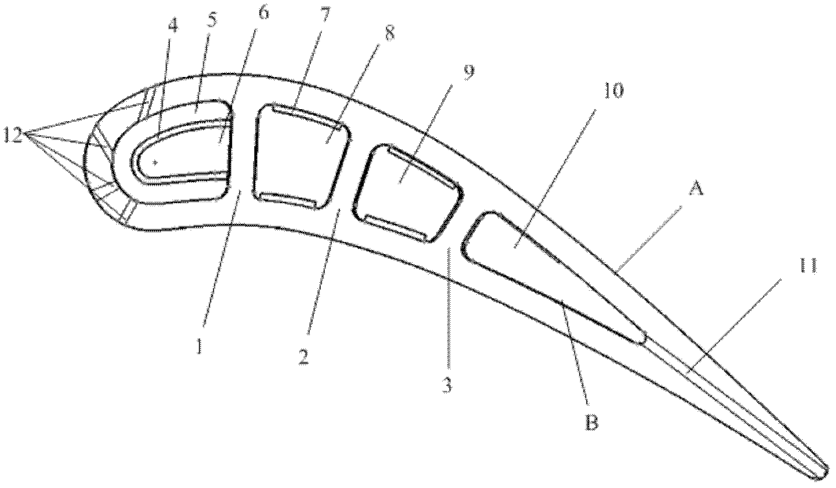
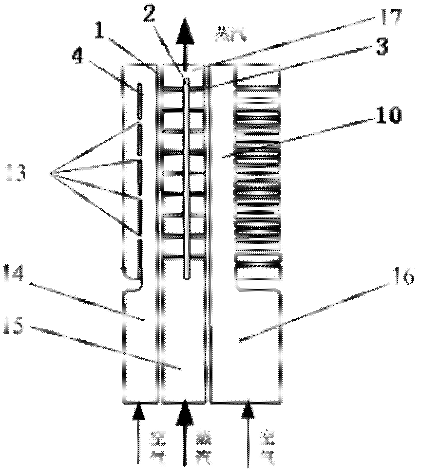
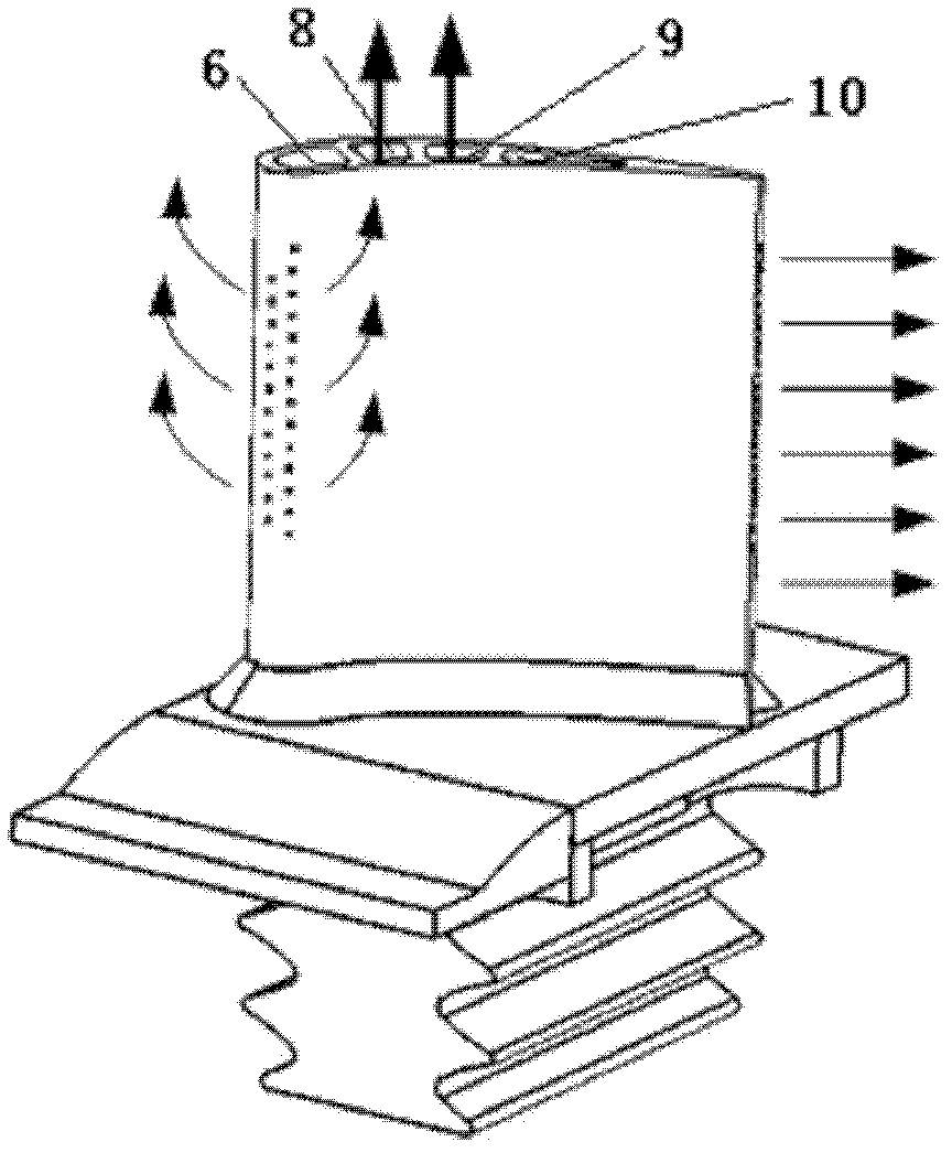
[0024] refer to figure 1 , figure 2 and Figure 4 , according to the aerodynamic parameters, the shape line of the outer wall A of the blade is composed of four parts: the leading edge, the trailing edge, the pressure edge and the suction edge. The pressure side and suction side are defined by high-order Bezier curves, and the leading edge and trailing edge of the blade are connected by arcs, and the connection is second-order differentiable. The positions of the pressure side and the suction side are both defined by their relative positions to the mid-arc, and the mid-arc is defined by a second-order Bezier curve. The high-order Bezier curves defining the pressure side and the suction side are controlled by parameters such as the leading edge radius control point, the trailing edge radius control point, the outlet edge wedge angle control point, and the ...


PUM


Abstract

The invention relates to a heavy-type combustion engine high-temperature turbine double-medium cooling blade, which is characterized in that: a first separation plate and a third separation plate are sequentially arranged from the front edge and the end edge of a blade inner cavity to divide the blade inner cavity into a front cooling space, a middle cooling space and a rear cooling space to be independent from one another along the radial direction of the blade, the blade front cooling space is divided by a fourth separation plate into a first cooling cavity and a second cooling cavity, impact cooling holes are equally distanced to one another to be arranged on the fourth separation plate, the front edge of the blade is provided with four rows of gas film cooling holes which are alternatively arranged, spoiler ribs which are arranged at equal intervals are arranged on a blade inner wall B of the middle cooling space, the middle cooling space is divided by a second separation plate into a third cooling cavity and a fourth cooling cavity, which are communicated with each other, the rear cooling space is a fifth cooling cavity, and the fifth cooling cavity is connected through fin-shaped vent holes which are equally distanced to one another; and the middle cooling space adopts a steam closed-type cycling cooling way to be combined with the air cooling way of the front and the rear cooling spaces, so the cooling fluid has high heat exchanging coefficient on each position of the blade, the cooling effect can be improved, and the unit heat efficiency can be improved.

Description

technical field [0001] The invention relates to a high-temperature turbine cooling blade of a gas turbine, in particular to a dual-substance cooling blade of a heavy-duty gas turbine high-temperature turbine, which is suitable for a heavy-duty gas turbine cooling blade of a steam-combustion combined cycle, and is applied to the first-stage stationary blade of a turbine blade Grid, to meet the cooling needs of high-temperature turbine blades of heavy-duty gas turbines. Background technique [0002] The thermal efficiency and power output of gas turbines increase with the increase of the turbine inlet temperature. However, the turbine blades work in the harsh environment of high temperature and heavy load. How to ensure the reliability of their operation is an important task for the majority of researchers. Using cooling fluid for effective cooling and developing new high-temperature-resistant materials (including thermal barrier coating material TBC) are two major measures fo...

Claims


Application Information

Patent Timeline
Patent Type & Authority Applications(China)
IPC IPC(8): F01D5/18F01D9/02F02C7/18
Inventor 徐亮高建民史晓军李云龙王维税琳棋李法敬
Owner XI AN JIAOTONG UNIV
Why Eureka
Try Eureka