Surface examination device

A surface inspection device, digital image technology, applied in the direction of measuring device, image data processing, instruments, etc., can solve the problems of time-consuming inspection and inability to know the range and size of polishing residues

Inactive Publication Date: 2012-04-25
HONDA MOTOR CO LTD
View PDF8 Cites 5 Cited by
  • Summary
  • Abstract
  • Description
  • Claims
  • Application Information

AI Technical Summary

Problems solved by technology

[0012] In this way, in the prior art, there is such a problem that only the degree of roughness of the entire inner surface of the cylinder bore can be known, but the range and size of the polishing residue cannot be known. As a result, it is necessary for the operator to visually find out where the polishing residue is, and it needs to be confirmed to make a judgment, and in addition, the inspection takes time

Method used


Image

  • Surface examination device
  • Surface examination device
  • Surface examination device

Examples


no. 1 Embodiment approach

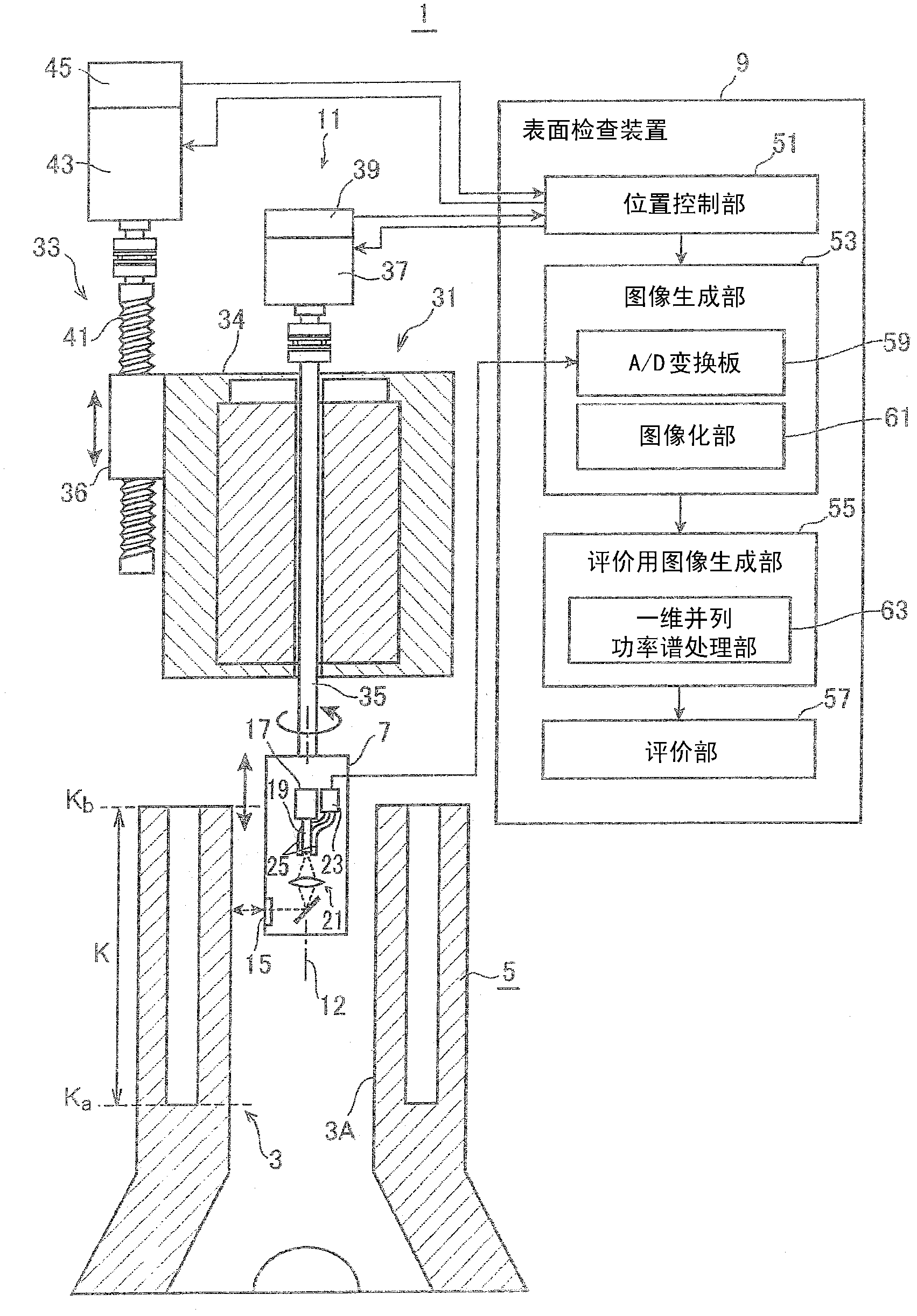
[0073] figure 1 It is a figure which shows the schematic structure of the cylinder bore inner surface inspection system 1 provided with the surface inspection apparatus 9 of this embodiment, and the cylinder block 5 in which the cylinder bore 3 which is an inspection object is formed.

[0074]The cylinder barrel 3 is formed by machining, that is, so-called boring machining, in which a cutting tool is radially protruded from a boring head provided on a rotating shaft, and the boring head is moved forward and backward with respect to the cylinder block 5 as a workpiece while rotating the boring head. form. By this boring process, directional helical cutting traces can be formed on the inner surface 3A of the cylinder barrel 3 . Thereafter, the inner surface 3A of the cylinder bore 3 is honed using a machining head equipped with a honing grindstone in order to obtain surface roughness and surface properties that allow the engine to exhibit desired performance while leaving oil p...

no. 2 Embodiment approach

[0112] In the prior art (Japanese Unexamined Patent Publication No. 2004-132900 ), image processing is performed on a digital image over the entire area of ​​the inner surface of the cylinder bore, which increases the time required for inspection and hinders the improvement of engine productivity. In addition, when foreign matter such as water droplets and dust is adsorbed on the inner surface of the cylinder bore, the foreign matter is reflected on a digital image and erroneously determined as a defect.

[0113] Therefore, in the present embodiment, the surface inspection apparatus 209 which is not affected by foreign matter on the surface and can reduce the time required for inspection by reliably narrowing the range to be subjected to image processing will be described.

[0114] Figure 8 It is a figure which shows the schematic structure of the cylinder bore inner surface inspection system 201 provided with the surface inspection apparatus 209 of 2nd Embodiment of this inv...

no. 3 Embodiment approach

[0141] When cutting the boring of the cylinder block, the forward and backward speed of the boring turning tool with respect to the cylinder block is not limited to be constant at all times. Therefore, since the pitch of the helical machining marks formed on the inner surface of the cylinder barrel changes according to the advancing and retracting speed, the directions of the machining marks are not the same.

[0142] On the other hand, in the prior art (Japanese Unexamined Patent Publication No. 2004-132900 ), the change in the light amount of the reflected light obtained by the scanning of the sensor head depends on the difference between the scanning direction of the sensor head and the direction of the machining traces. offset. That is, when the sensor head is scanned in the direction of the machining mark, the change in the amount of reflected light is small, and the change in the amount of reflected light increases as the angle intersecting the direction of the machining...


PUM


Abstract

A deep machining scratch is detected, if any, the position and size can be inferred, and thereby the examination time can be shortened. A surface examination device (9 )for examining the inner surface (3A) of a bore (3) formed in a cylinder block (5) by boring and honed on the basis of a digital brightness image (70) of the inner surface (3A) is provided with an evaluation image creating unit (55) for creating linear power spectrum images (71) in a direction perpendicular to the direction of the cutting scratch (P) along the direction of the cutting scratch (P) from the digital brightness image (70), arranging the linear power spectrum images (71) parallel, and thus creating an evaluation image (73) and evaluating unit (57) for evaluating the presence / absence of an unhoned region (Q) of the inner surface (3A) of the bore (3); on the basis of the pixel values of the pixels of the evaluating image (73).

Description

technical field [0001] The present invention relates to a surface inspection apparatus for inspecting the surface of a machined workpiece. Background technique [0002] In the manufacturing process of an automobile, a cylinder bore is machined on a cylinder block of an engine, and then a cylinder head, a crankcase, etc. are attached to the cylinder block to assemble the engine. The machining of the cylinder barrel is performed by boring machining in which the boring turning tool advances and retreats with respect to the cylinder block while rotating to form the cylinder barrel. Since a helical machining mark is left on the inner surface of the cylinder barrel by using the boring machining for the cutting machining of the cylinder barrel, the machining mark can be utilized as an engine oil passage (oil pit). . [0003] However, since the inner surface of the cylinder bore serves as the sliding surface of the piston, in order to suppress the sliding resistance and achieve th...

Claims


Application Information

Patent Timeline
Patent Type & Authority Applications(China)
IPC IPC(8): G01N21/954G01N27/90
CPCG06T2207/20048G06T7/0002G06T2207/30164G06T7/0004G01N21/954G01N27/90
Inventor 及川聪野条聪
Owner HONDA MOTOR CO LTD
Why Eureka
Try Eureka