Speed-measuring radar system with function of distinguishing vehicle direction

A speed measuring radar and vehicle direction technology, which is applied in the field of speed measuring radar system, can solve the problems of low radiation efficiency, power loss, increase the hidden danger of traffic accidents, inability to distinguish speeding vehicles, etc., and achieve the effects of excellent performance, compact structure and small size.

Inactive Publication Date: 2012-05-09
安徽蓝盾光电子股份有限公司
View PDF5 Cites 7 Cited by
  • Summary
  • Abstract
  • Description
  • Claims
  • Application Information

AI Technical Summary

Problems solved by technology

[0003] The defects of the existing speed measuring radar are as follows: it only works in a single mode to complete complex and accurate information collection, and there is a high cost; in the highway speed measuring radar, when there are cars running on the two lanes at the same time, and the direction is opposite, only It can detect speeding vehicles, but cannot distinguish speeding vehicles. In order to avoid misjudgment, we can only give up the capture, which virtually increases the hidden danger of traffic accidents; when the speed radar receiving signal is converted from radio frequency to intermediate frequency in the receiver, most of them have no additional If the processing is performed, the sign of the Doppler frequency shift will be lost, and the direction of motion (approaching or moving away) relative to the target will not be determined; due to the reduction in the volume of the speed measuring radar antenna, most of the printed planar antennas are used, and the outline Small and lightweight, but has low radiation efficiency and severe power loss due to its severe conductor loss

Method used


Image

  • Speed-measuring radar system with function of distinguishing vehicle direction
  • Speed-measuring radar system with function of distinguishing vehicle direction

Examples


Embodiment Construction

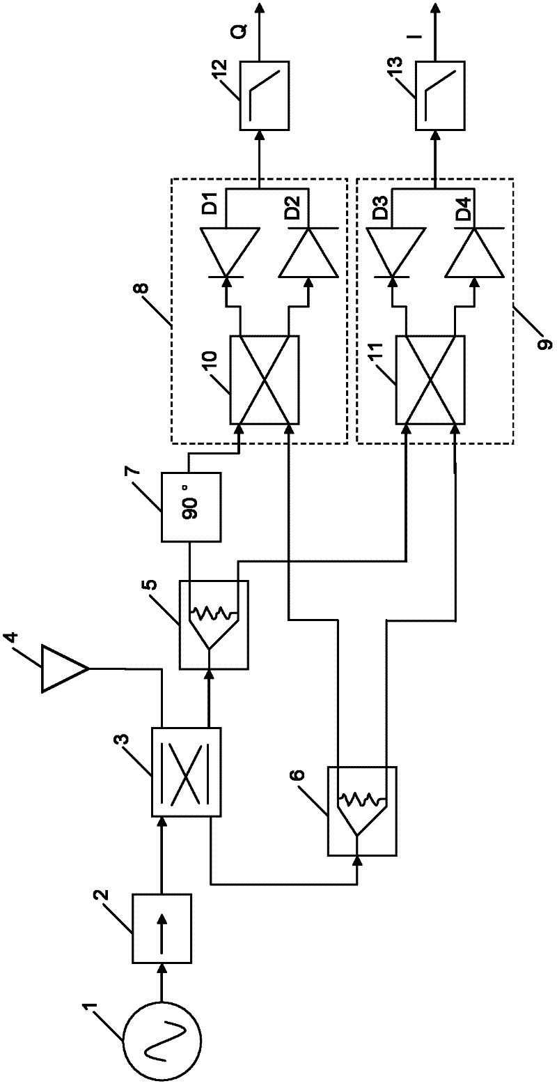
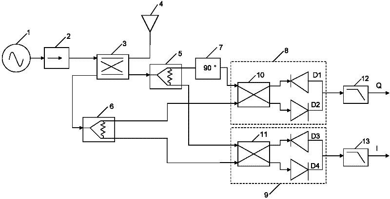
[0008] A speed measuring radar system with a vehicle direction discrimination function, comprising a frequency source 1, the frequency source 1 is connected to the input end of a branch line coupler 3, the branch line coupler 3 is connected to a transceiver antenna 4, and the coupling port of the branch line coupler 3 Connected to the first and second power dividers 5 and 6 respectively, the first power divider 5 is divided into two outputs, one is connected to the first mixer 8 through a 90° delay line 7, and the other is connected to the second mixer 9 The output terminals of the second power divider 6 are connected to the first and second mixers 8 and 9 respectively. The output end of the first mixer 8 is connected with the input end of the first low-pass filter 12, and the output end of the second mixer 9 is connected with the input end of the second low-pass filter 13, as figure 1 shown.

[0009] Such as figure 1 As shown, the output end of the frequency source 1 is con...


PUM


Abstract

The invention relates to a speed-measuring radar system with a function of distinguishing a vehicle direction, and the system comprises a frequency source, wherein the frequency source is connected to the input end of a branch line coupler; a transceiving antenna is connected to the branch line coupler; the coupling port of the branch line coupler is respectively connected to a first power divider and a second power divider; the first power divider is used for outputting in two paths; one path is connected to a first frequency mixer through a 90-degree delay line; the other path is connected to a second frequency mixer; and the output end of the second power divider is respectively connected to the first and second frequency mixers. The speed-measuring radar system provided by the invention is low in production cost, compact in structure, small in volume, high in stability, excellent in property and reliable in circuit property; compared with other speed-measuring radar systems, the speed-measuring radar system has the characteristics of low cost and high efficiency; and the speed-measuring radar system can be used for detecting the overspeed of a vehicle and can be widely applied to a police snap-shooting speed-measuring system.

Description

technical field [0001] The invention relates to a speed measuring radar system, in particular to a speed measuring radar system with a vehicle direction discrimination function. Background technique [0002] With the rapid development of highway traffic, the safety problem on the highway has become extremely serious. Speeding and high traffic accident rate are the main reasons for traffic accidents. In order to reduce traffic accidents and violations caused by speeding, the speed measuring radar is used to detect the driving speed. The speed measuring radar uses the Doppler effect to measure the measurement speed. Law enforcement monitors, detects and records the speeding behavior of vehicles, and effectively curbs traffic accidents caused by speeding through severe punishment measures. [0003] The defects of the existing speed measuring radar are as follows: it only works in a single mode to complete complex and accurate information collection, and there is a high cost; i...

Claims


Application Information

Patent Timeline
Patent Type & Authority Applications(China)
IPC IPC(8): G01S13/58G01S7/28
Inventor 陈建设王飞贺德溪
Owner 安徽蓝盾光电子股份有限公司
Why Eureka
Try Eureka