
Focusing and leveling system capable of timely compensating wave-front distortion and compensation method thereof

A technology of focusing and leveling, wavefront distortion, applied in the field of lithography, can solve the problems affecting measurement accuracy, spot position shift, disturbance, etc.

Inactive Publication Date: 2012-05-09
SHANGHAI MICRO ELECTRONICS EQUIP (GRP) CO LTD
View PDF3 Cites 2 Cited by
  • Summary
  • Abstract
  • Description
  • Claims
  • Application Information

AI Technical Summary

Problems solved by technology

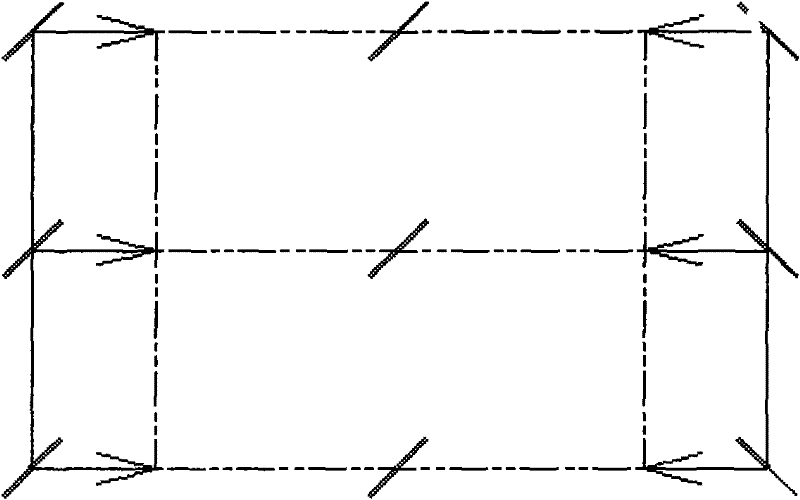
However, in practical applications, through optical simulation, due to the difference in temperature and air pressure around the focusing and leveling system or the modules of the focusing and leveling optical system, the incident light wavefront is distorted and the position of the spot is shifted, such as figure 1 shown
At the same time, due to processing and other issues, the optical system itself also has its own distortion.
However, this patent cannot solve the problem of random changes in the environment and the distortion of the optical system itself causing the position of the spot to shift.
[0003] As the precision of lithography equipment is getting higher and higher, the measurement spot of the focusing and leveling optical system is required to be smaller and smaller. When there are many measurement spots, the refractive index of air and glass, spacers, etc. The thermal expansion coefficient of the material such as changes, and the change in the refractive index of the air will cause airflow or atmospheric disturbance, resulting in distortion of the light wave front, reducing the image quality, changing the position of the spot, and changing the refractive index of materials such as glass and spacers. After the change, the radius of curvature and the thickness of the glass will change, which will also cause distortion of the light wave front, reduce the image quality, and change the position of the spot, making it difficult to achieve accurate matching between the spot and the slit
Affected the measurement accuracy

Method used


Image

  • Focusing and leveling system capable of timely compensating wave-front distortion and compensation method thereof
  • Focusing and leveling system capable of timely compensating wave-front distortion and compensation method thereof
  • Focusing and leveling system capable of timely compensating wave-front distortion and compensation method thereof

Examples


no. 1 example

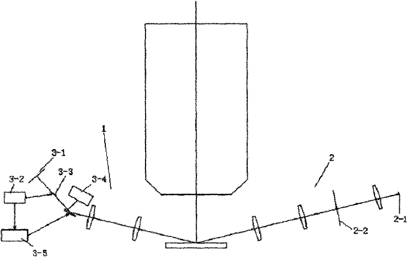
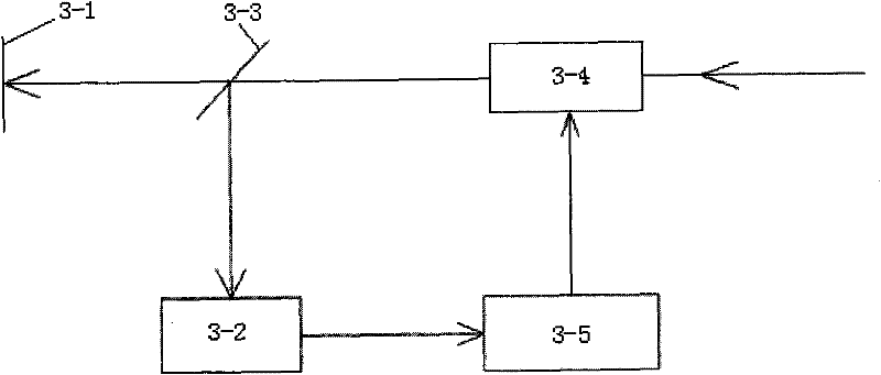
[0049] figure 2 Shown is a schematic structural view of the focusing and leveling system according to the present invention. The system inserts a closed-loop system into the existing focusing and leveling optical path. The closed-loop system consists of a wavefront sensor 3-2, a wavefront controller 3 -5 and wavefront corrector 3-4 are composed of three parts, such as image 3 shown.

[0050] Among them, the wavefront sensor 3-2 is used to detect wavefront errors in real time. The wavefront sensor 3-2 should have high precision and weak light detection capability. For example, a dynamic Hartmann-Shack wavefront sensor can be used, which consists of a microlens array 4-1 and an array detector 4-2. Figure 4 for its schematic diagram.

[0051] The wavefront controllers 3-5 are mainly used for wavefront restoration and generation of control signals.

[0052] The wavefront corrector 3-4 is mainly used to convert the control signal provided by the wavefront controller 3-5 int...

no. 2 example

[0088] The entire closed-loop system in another embodiment of the present invention consists of three parts: a wavefront sensor, a wavefront controller and a wavefront corrector, wherein the wavefront sensor and wavefront controller are similar to those of the first embodiment. Wavefront correctors 3-4 employ Figure 7 structure shown. It is made up of a plurality of small mirrors that can be independently translated or translated and tilted, and has a relatively large dynamic range of the wavefront. It can achieve high-speed and high-precision optical mirror surface shape change, translation or rotation angle under external control, thereby changing the wavefront phase of the optical system.


PUM


Abstract

The invention discloses a focusing and leveling system capable of timely compensating wave-front distortion and a compensation method thereof. The system comprises a projection side and a detection side; and the light beam from the protection side is reflected by a silicon wafer surface and then imaged through a detection slit surface of the detection side. The system is characterized in that a closed loop wave-front compensation system which comprises a wave-front sensor, a wave-front controller and a wave-front corrector; the optical path of the light beam to the wave-front sensor is as same as that to the detection slit surface; after the light beam enters the wave-front corrector, the corrected light beam is divided into two parts, wherein the major part of the light beam is imaged on the detection slit surface and the small part of the light beam enters the wave-front sensor; then the wave-front sensor is used for timely detecting a wave-front error; and then the wave-front controller is used for driving the wave-front corrector to carry out wave-front correction according to error signals detected by the wave-front sensor.

Description

technical field [0001] The invention relates to the field of lithography, in particular to a focusing and leveling system capable of real-time compensation of wavefront distortion applied in a lithography system. Background technique [0002] At present, in the field of lithography, the position information of the silicon wafer is mainly measured by the focusing and leveling optical system, and then the position information is fed back to the workpiece table, so that the position of the silicon wafer is controlled according to the information, so that the focal plane of the silicon wafer and the projection objective lens coincide. For example, the patent 5633721 of Nikon Corporation of Japan provides a focusing and leveling optical system for measuring the spot position. However, in practical applications, through optical simulation, due to the difference in temperature and air pressure around the focusing and leveling system or the modules of the focusing and leveling optic...

Claims


Application Information

Patent Timeline
IPC IPC(8): G03F9/00
Inventor 卢丽荣李志丹徐兵陈飞彪
Owner SHANGHAI MICRO ELECTRONICS EQUIP (GRP) CO LTD
Learn More