Liquid crystal module test device with display port (DP) interface and test method thereof

A liquid crystal module and testing device technology, which is applied in the direction of measuring devices, measuring electricity, and measuring electrical variables, etc., can solve the problems of unfavorable liquid crystal module automatic testing and rapid production change, reduce test efficiency, and cannot support at the same time, so as to improve production Efficiency and product qualification rate, improve test efficiency and test reliability, and save test cost

Active Publication Date: 2012-05-09
WUHAN JINGCE ELECTRONICS GRP CO LTD
View PDF7 Cites 32 Cited by
  • Summary
  • Abstract
  • Description
  • Claims
  • Application Information

AI Technical Summary

Problems solved by technology

However, due to the complexity of the design architecture and the limitation of the use of dedicated chips, the traditional LCD module test equipment has a single function and can only support the LVDS interface. It cannot support the LVDS interface and the DP interface at the same time, nor can it support the external input test signal source and the built-in test at the same time. Signal source, the traditional liquid crystal module testing device does not

Method used


Image

  • Liquid crystal module test device with display port (DP) interface and test method thereof
  • Liquid crystal module test device with display port (DP) interface and test method thereof
  • Liquid crystal module test device with display port (DP) interface and test method thereof

Examples


Embodiment Construction

[0032] The present invention will be described in further detail below in conjunction with the accompanying drawings and embodiments.

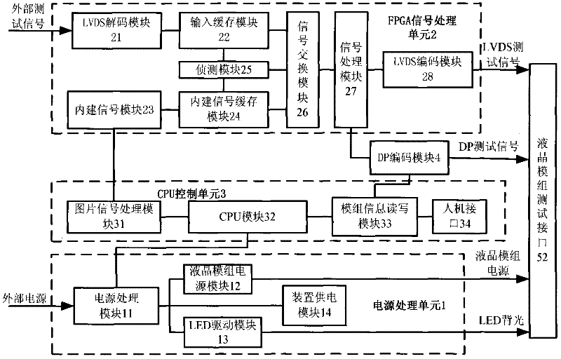
[0033] Such as figure 1 As shown, the liquid crystal module testing device with DP interface of the present invention includes a power processing unit 1, an FPGA (Field-Programmable Gate Array, Field Programmable Gate Array) signal processing unit 2, a CPU control unit 3, and a DP encoding module 4, The power processing unit 1, the FPGA signal processing unit 2 and the DP encoding module 4 are connected to a liquid crystal module test interface 5, and the liquid crystal module test interface 5 is connected to the liquid crystal module to be tested (not shown).

[0034] The power processing unit 1 includes a power processing module 11 for external input power filtering processing, a liquid crystal module power module 12 connected to the power processing module 11, an LED driver module 13 and a device power supply module 14, and a liquid crystal...


PUM


Abstract

The invention discloses a liquid crystal module test device with a display port (DP) interface and a test method thereof, which relate to the test field of liquid crystal modules. The liquid crystal module test device with the DP interface comprises a power supply processing unit, a field programmable gate array signal processing unit and a central processing unit (CPU) control unit, wherein the power supply processing unit and the field programmable gate array signal processing unit are connected with one liquid crystal module test interface; the liquid crystal module test interface is connected with a liquid crystal module to be tested; the power supply processing unit comprises a power supply processing module and a light emitting diode (LED) driving module; the CPU control unit and the field programmable gate array signal processing unit are both connected with one DP coding module which outputs a signal to the liquid crystal module to be tested; and the field programmable gate array signal processing unit comprises a built-in signal module, a low-voltage differential signaling decoding module and a low-voltage differential signaling coding module. According to the test device and the test method, a low-voltage differential signaling (LVDS) interface and the DP interface are simultaneously provided, an external input test signal and a built-in test signal are simultaneously supported, and LED backlight driving output is provided.

Description

technical field [0001] The invention relates to the testing field of liquid crystal modules, in particular to a liquid crystal module testing device and a testing method with a DP interface. Background technique [0002] LCD (Liquid Crystal Display, liquid crystal display) includes LED (Light Emitting Diode, light emitting diode) backlit liquid crystal display and CCFL (Cold Cathode Fluorescent Lamp, cold cathode fluorescent lamp) backlit liquid crystal display. LCD, especially LED-backlit liquid crystal display, has many advantages such as light and thin, low power consumption, low radiation, no flickering on the screen, and rich colors. market share. The main component of the LCD is a liquid crystal module (LCD Module), and the internal interconnection signal of the LCD module adopts LVDS (Low-Voltage Differential Signaling, low-voltage differential signal) or DP (DisplayPort, display interface) interface mode. The DP interface adds support for high-definition audio sign...

Claims


Application Information

Patent Timeline
IPC IPC(8): G09G3/00G01R31/00
Inventor 彭骞陈凯周凯
Owner WUHAN JINGCE ELECTRONICS GRP CO LTD
Why Eureka
Try Eureka