Composite material part having a ceramic matrix, and method for manufacturing same

A technology of ceramic matrix and composite materials, which is applied in the direction of thin material processing, layered products, transportation and packaging, etc. It can solve the problems of the limitation of self-healing matrix cohesion, reduce the risk of peeling, and enhance the effect of resistance

Inactive Publication Date: 2012-05-23
GERAKL
View PDF7 Cites 3 Cited by
  • Summary
  • Abstract
  • Description
  • Claims
  • Application Information

AI Technical Summary

Problems solved by technology

[0007] However, the effectiveness of the self-healing matrix phase is limited to a specific temperature range

Method used


Image

  • Composite material part having a ceramic matrix, and method for manufacturing same
  • Composite material part having a ceramic matrix, and method for manufacturing same
  • Composite material part having a ceramic matrix, and method for manufacturing same

Examples


Embodiment 1

[0090] An ensemble is made on a silicon substrate: SiC / SiC+PyC interface / SiC / SiC+PyC interface / SiC, wherein:

[0091] - the SiC layer is prepared in a known manner from MTS+H by CVI at a temperature of about 1000°C and a pressure of about 5 kPa 2 The stoichiometric layer obtained in the gas phase, H 2 The ratio α between the ratio and the MTS ratio is about 6,

[0092] - The SiC+PyC interface from MTS+H via CVI 2 obtained in the gas phase, resulting in a first exfoliated phase PyC with a layered structure and a second phase consisting of PyC crystallites, under the same conditions as those leading to obtaining stoichiometric SiC, except for the ratio α, which was chosen to be 1 the following.

[0093] For the formation of each interface, by choosing a ratio α equal to approximately 0.1 (full) and a duration of 1.5 minutes, an interface with a thickness approximately equal to 30 nm and containing 80% atoms of PyC (the rest formed by SiC crystallites) is obtained.

[0094] ...

Embodiment 2

[0096] Using the same procedure as in Example 1, but using a ratio α approximately equal to 0.25 and a duration of 5 minutes during the preparation of each interface, a SiC+PyC with a thickness approximately equal to 0.3 microns and containing 70% atoms is obtained The interface of PyC (the rest is formed by SiC crystallites).

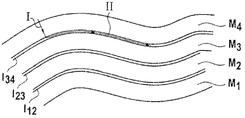
[0097] Figure 10 The path of the crack caused by the dent under load is shown. It can be seen that there is no transition from Mode I to Mode II in the second interface, and this transition redirected to Mode I occurs in the first interface.

Embodiment 3

[0099] Using the same procedure as in Example 1, but using a ratio α approximately equal to 0.5 and a duration of 5 minutes during the preparation of each interface, a PyC having a thickness approximately equal to 0.2 μm and containing 60% atoms (the remainder Formed from SiC crystallites) at the SiC+PyC interface.

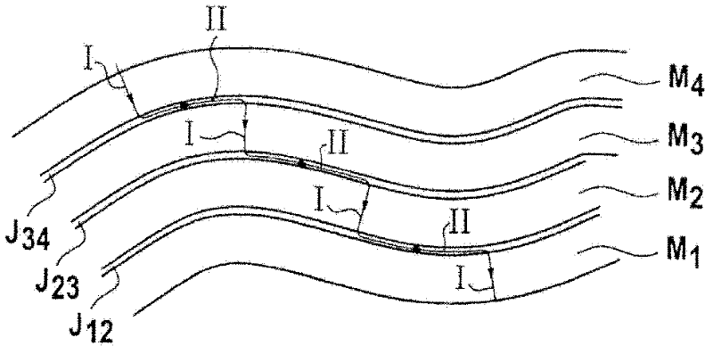
[0100] Figure 11 The path of the crack caused by the dent under load is shown. It can be seen that there is no transition from mode I to mode II in both interfaces, which reflects the insufficient existence of the exfoliated phase.


PUM

PropertyMeasurementUnit
thicknessaaaaaaaaaa
diameteraaaaaaaaaa
heightaaaaaaaaaa

Abstract

In a composite material part having a ceramic matrix and including a fibrous reinforcement which is densified by a matrix consisting of a plurality of ceramic layers having a crack-diverting matrix interphase positioned between two adjacent ceramic matrix layers, the interphase (10) includes: a first phase (12) made of a material conducive to the diversion of a crack reaching the interphase according to a first propagation mode in the transverse direction through one of the two ceramic matrix layers adjacent to the interphase, such that the propagation of the crack continues according to a second propagation mode along the interphase; and a second phase consisting of discrete contact pads (14) that are distributed within the interphase and conducive to the diversion of the crack that propagates along the interphase according to the second propagation mode, such that the propagation of the crack is diverted and continues according to the first propagation mode through the other ceramic matrix layer that is adjacent to the interphase.

Description

technical field [0001] The present invention relates to composite parts having a ceramic matrix, particularly, but not exclusively, to parts for aeroengines or rocket engines. Background technique [0002] Ceramic matrix composites (CMC) consist of fiber reinforcements (carbon fibers or ceramic fibers) densified by a ceramic matrix. The mechanical properties and temperature resistance of ceramic matrix composites make them suitable for use in structural components exposed to high temperatures during use. [0003] However, under the action of thermomechanical stress, often during the preparation of CMC, CMC is prone to cracking. In order to avoid fragmentation of the fibers of the fiber reinforcement due to crack propagation through the matrix, and in order to avoid the rapid deterioration of the mechanical properties resulting therefrom, it is known to provide an embrittlement-mitigating interface between the fibers and the matrix. Such an interface is usually made of a ma...

Claims


Application Information

Patent Timeline
Patent Type & Authority Applications(China)
IPC IPC(8): B32B5/22C04B35/565C04B35/80C04B41/45C04B35/628C04B41/52C04B35/52
CPCC04B35/6286C04B35/62894C04B41/87C04B35/806C04B2235/614C04B35/62884C04B41/009C04B35/80C04B35/62873C04B35/62897C04B2235/616C04B35/62868C04B41/5059C04B35/62863Y10T428/249928C04B37/005C04B2237/365C04B2237/592C04B35/565C04B41/4531C04B41/4572B32B5/26
Inventor J·泰博S·贝特朗
Owner GERAKL
Why Eureka
Try Eureka