Air cushion device
An air cushion and airbag technology, which is applied to liquid-filled cushions and the measurement of force by measuring the change of optical properties of materials when they are stressed, can solve problems such as limiting the use range of the device, losing the sensing function, and blocking the optical path. Good resistance, improved comfort, and high test accuracy
- Summary
- Abstract
- Description
- Claims
- Application Information
AI Technical Summary
Problems solved by technology
Method used
Image
Examples
Embodiment 1
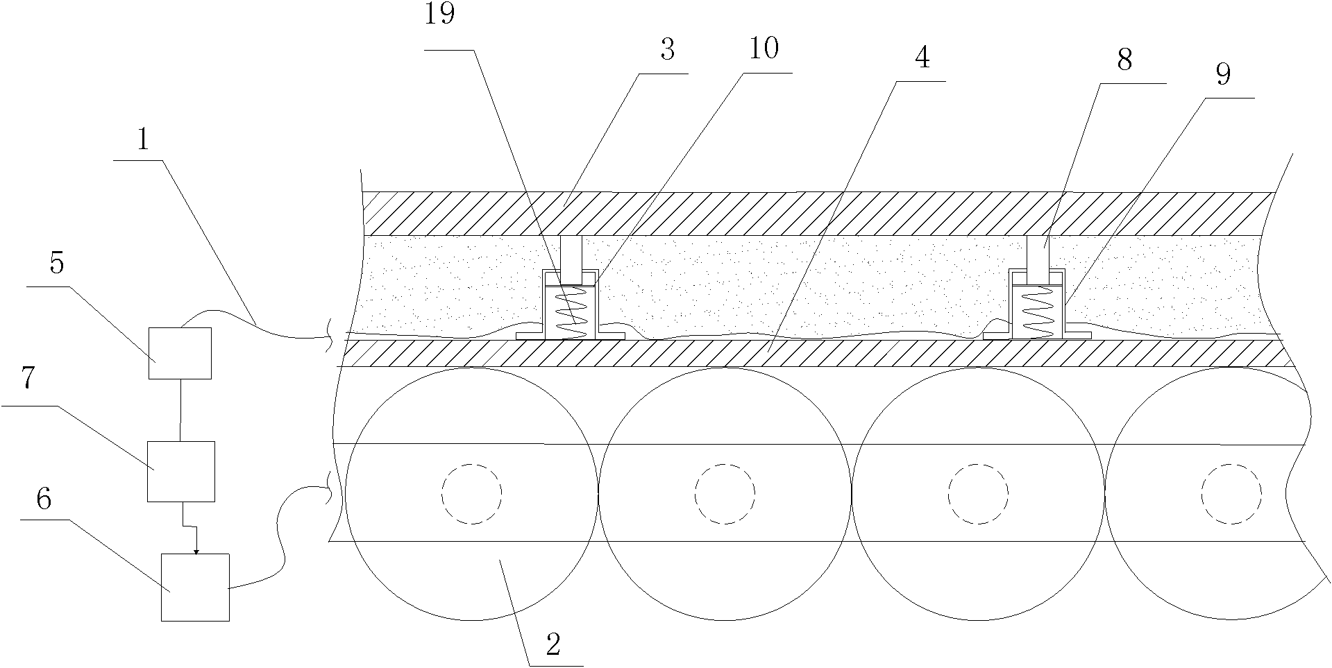
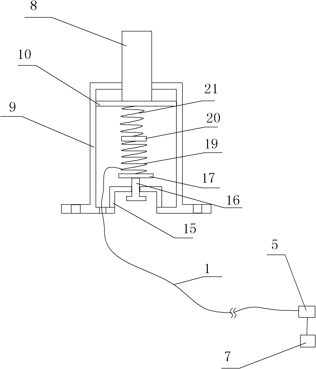
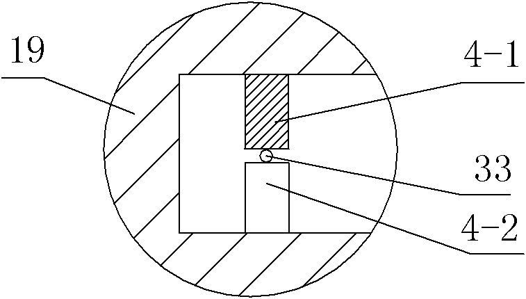
[0041] Such as figure 1 , figure 2 , image 3 with Figure 4 The shown air cushion device includes an elastic plate and a plurality of airbags 2, the plurality of airbags 2 are connected with an air pump 6, the elastic plate is located on the upper surface of the plurality of airbags 2, and the elastic plate includes an upper surface plate 3 , the lower surface plate 4, a filler 35 is arranged between the upper surface plate 3 and the lower surface plate 4, and a plurality of curved brackets are arranged in the filler 35, and the inside of the curved bracket is arranged on opposite sides There are multiple A-side deformed teeth 4-1 and multiple B-side deformed teeth 4-2, and the multiple A-side deformed teeth 4-1 and multiple B-side deformed teeth 4-2 are arranged in a staggered manner, and the heads of the two A curved passage for one or more signal optical fibers 33 is formed between the parts, and the A-side deformed teeth 4-1 and the B-side deformed teeth 4-2 are corre...
Embodiment 2
[0049] Such as Figure 4 , Figure 5 As shown, in this embodiment, the difference from Embodiment 1 is that the curved support is a spring 38, and the deformation teeth 4-1 on the A side and the deformation teeth 4-2 on the B side are arranged adjacent to each other in the spring 38. Between the two coils of spring wire, the deformation teeth 4-1 on the A side and the deformation teeth 4-2 on the B side are alternately arranged. In this embodiment, the structures, connections and working principles of other parts are the same as those in Embodiment 1.
Embodiment 3
[0051] Such as Image 6 , Figure 7 As shown, in this embodiment, the difference from Embodiment 1 is that the curved bracket is a bellows 40, and the deformation teeth 4-1 on the A side and the deformation teeth 4-2 on the B side are correspondingly arranged on the pipe wall of the bellows 40 On the two opposite side surfaces of the inner recess on 41, the A-side deformed teeth 4-1 and the B-side deformed teeth 4-2 are alternately arranged. In this embodiment, the structures, connections and working principles of other parts are the same as those in Embodiment 1.
PUM
 Abstract
Description
Claims
Application Information
 - R&D
- Intellectual Property
- Life Sciences
- Materials
- Tech Scout
- Unparalleled Data Quality
- Higher Quality Content
- 60% Fewer Hallucinations
Browse by: Latest US Patents, China's latest patents, Technical Efficacy Thesaurus, Application Domain, Technology Topic, Popular Technical Reports.
© 2025 PatSnap. All rights reserved.Legal|Privacy policy|Modern Slavery Act Transparency Statement|Sitemap|About US| Contact US: help@patsnap.com


