Thermocompressor system

A thermal compressor, radiator technology, applied in the field of air-conditioning compressors

Inactive Publication Date: 2012-06-06
TECHNICAL INST OF PHYSICS & CHEMISTRY - CHINESE ACAD OF SCI
View PDF5 Cites 5 Cited by
  • Summary
  • Abstract
  • Description
  • Claims
  • Application Information

AI Technical Summary

Problems solved by technology

[0011] The technical problem to be solved by the present invention is to provide power for the heat-driven refrigeration system and the pulse tube refrigeration system in the air-conditioning temperature zone. It has the adaptability of various fuels, good environmental characteristics and high conversion efficiency, and the power structure is simple. Energy saving, less environmental pollution

Method used


Image

  • Thermocompressor system
  • Thermocompressor system
  • Thermocompressor system

Examples


Embodiment Construction

[0029] The specific implementation manners of the present invention will be further described in detail below in conjunction with the accompanying drawings and embodiments. The following examples are used to illustrate the present invention, but are not intended to limit the scope of the present invention.

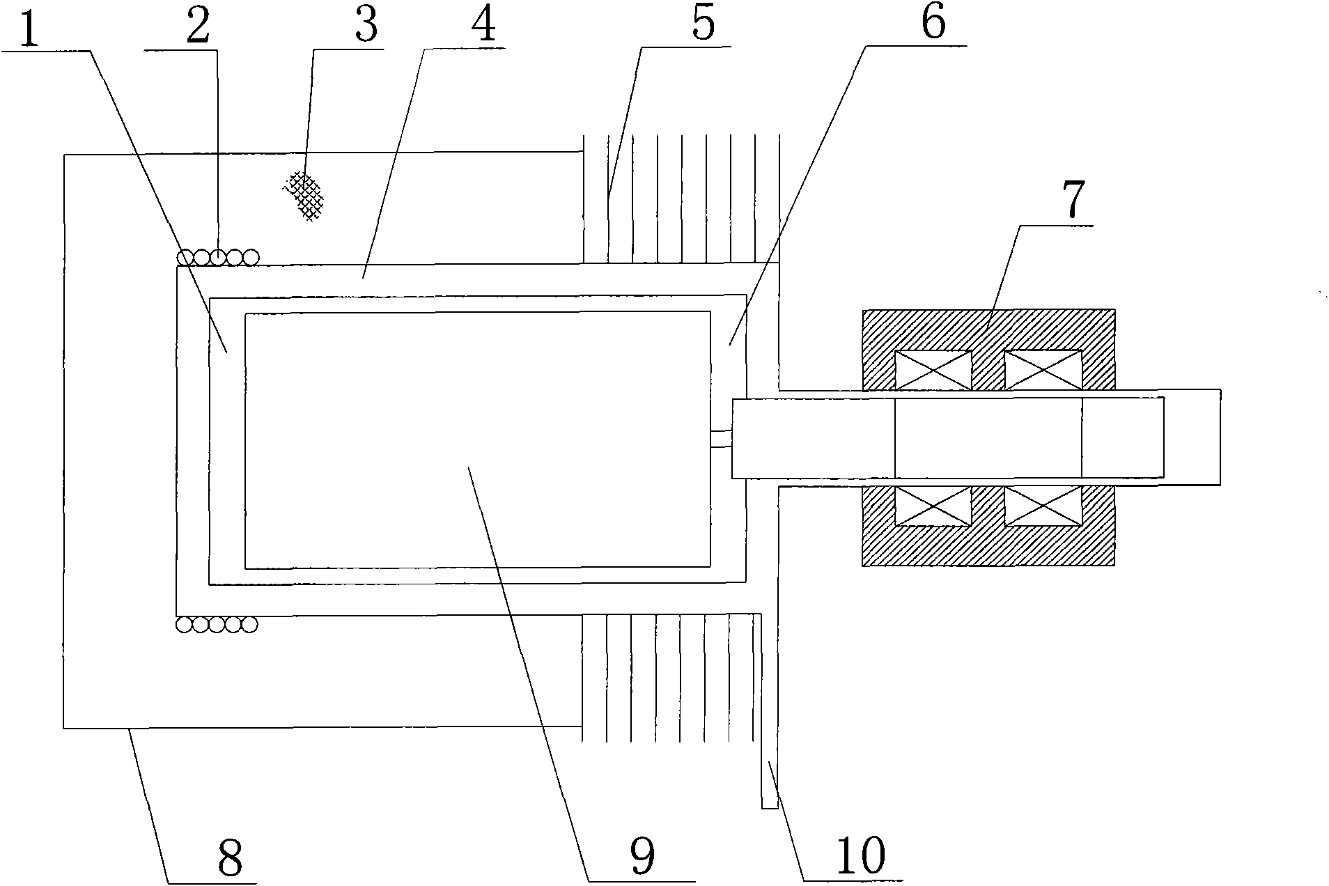
[0030] figure 1 A schematic structural diagram of a thermal compressor system according to an embodiment of the present invention is shown. As shown in the figure, the compressor system includes: a heater 2, an insulation layer 3, a cylinder body 4, a radiator 5, a linear motor 7, a casing 8, a piston 9, and a load connection port 10, and the piston 9 is located in the cylinder body 4 of the cylinder. Inside, the main shaft of the linear motor 7 is connected to the piston 9; when one end of the cylinder close to the linear motor 7 is defined as the top of the cylinder, and the opposite end is defined as the bottom of the cylinder, the heater 2 is arranged outside the bott...


PUM


Abstract

The invention discloses a thermocompressor system which comprises a cylinder, a piston and a linear motor. The piston is positioned in a cylinder body of the cylinder; a spindle of the linear motor is connected with the piston; the end of the cylinder, which is close to the linear motor, is defined into a cylinder body top end and the other opposite end of the cylinder is defined into a cylinder body bottom end; a heater is arranged outside the cylinder body bottom end of the cylinder; a radiator is arranged outside the cylinder body top end of the cylinder; and a working medium is filled in the cylinder body. According to the invention, the linear motor and a thermocompressor are coupled to work and the piston is driven by the linear motor to reciprocate in the cylinder of the thermocompressor so as to push gas to periodically flow between the cold and hot end parts of the cylinder; the cylinder adopts an external heat source to heat the hot end of the cylinder and various energy resources can be utilized; a differential pressure almost does not exist at both ends of the piston and the friction resistance in the reciprocating process of the piston can be overcome only by using the low-power linear motor; and the system has low vibration noise and low emission pollution and has excellent environment properties.

Description

technical field [0001] The invention relates to the field of air conditioner compressors and the field of pulse tube refrigeration system driving compressors, in particular to a system requiring a certain pressure amplitude, specifically a thermal compressor system. Background technique [0002] With the economic development of our country and the energy shortage around the world, energy conservation, emission reduction and improvement of energy utilization efficiency have become a challenging task. In this process, the recovery and reuse of waste heat has a very large market and significance. Power plants, chemical plants, steel plants, etc. all produce a large amount of waste heat, and the most easily available solar energy generally only provides a lower heat source temperature. The annual sales volume of air conditioners in China exceeds 20 million units, most of which are driven by electricity, which puts heavy pressure on the power supply and distribution of cities. ...

Claims


Application Information

Patent Timeline
Patent Type & Authority Applications(China)
IPC IPC(8): F02G1/055
Inventor 杨鲁伟吴小华杨俊玲林文野
Owner TECHNICAL INST OF PHYSICS & CHEMISTRY - CHINESE ACAD OF SCI
Why Eureka
Try Eureka