
Underground mine water treatment method

A treatment method and mine water technology, applied in the field of environmental engineering, can solve the problems of large area of ​​mine water treatment facilities, long hydraulic retention time in sedimentation tanks, large investment in power equipment and pipelines, etc., so as to improve the technical level of resource utilization. , reduce energy consumption and the amount of chemical agents, and solve the effect of water shortage in production

Active Publication Date: 2012-06-13
CHINA UNIV OF MINING & TECH
View PDF2 Cites 11 Cited by
  • Summary
  • Abstract
  • Description
  • Claims
  • Application Information

AI Technical Summary

Problems solved by technology

At present, most mine water treatment systems are built on the ground, occupying a large area, the lifting of mine water and the reuse of underground water after ground treatment have a long transportation distance, the investment in power equipment and pipelines is large, and the energy consumption is high; the commonly used treatment process for mine water Mainly: sedimentation, coagulation sedimentation, coagulation sedimentation + filtration, etc. There are many problems in the treatment of mine water by conventional processes: (1) The mine water mainly contains suspended solids mainly composed of coal dust, which has an alum flower structure formed after dosing Due to the characteristics of looseness and slow settling speed, due to the slow settling process of flocs and long hydraulic retention time in sedimentation tanks, mine water treatment facilities occupy a large area; The cost of water treatment is high, and the secondary pollution increases with the increase of the amount of chemical used

Method used


Image

  • Underground mine water treatment method
  • Underground mine water treatment method

Examples


Embodiment Construction

[0014] Embodiments of the present invention will be further described below in conjunction with the accompanying drawings:

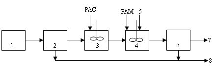
[0015] The underground treatment method of mine water in the present invention: the mine water in the underground water tank 1 is pumped into the swirl desanding tank 2 by a pump, the mine water rotates at a fast speed along the tangential direction to generate centrifugal force, and under the action of centrifugal force and gravity , the coarser particulate matter sinks into the sand bucket along the pool wall to be removed; the mine water from which the particulate matter is removed is introduced into the coagulation reaction tank 3, and 10mg / l Inorganic flocculant (PAC), and stirred at a stirring speed of 200 rpm, the coagulation reaction forms alum flowers, the mine water after the coagulation reaction is introduced into the mixing tank 4, and 0.5mg / l organic coagulation aid (PAM) and 1.5g / l The particle size is 70-150 mesh fly ash or coal gangue...


PUM


Abstract

The invention discloses an underground mine water treatment method. Mine water passes through a cyclone degritting tank first, enters a coagulation tank after larger coal particles are removed, and then enters a mixing tank after alum flocs are formed when chemical flocculating agent is added into the coagulation tank, and meanwhile, organic coagulant aid and coal ash with certain particle size or smashed coal gangue with certain particle size are added into the mixing tank, sludge and water are separated after compact flocs are formed in a sedimentation tank. Water discharged from the sedimentation tank can be used for underground production or be lifted to the ground for recycling, and solid matters separated in the cyclone degritting tank and the sedimentation tank can be backfilled tounderground discarded roadways. The method is small in occupied area and high in treatment efficiency, no ground area needs to be occupied, underground mine water treatment and recycling can be realized, costs of power equipment and pipeline delivery for the mine water lifting and recycling underground can be reduced, and energy consumption and flocculating agent usage can be reduced. Further, the coal ash or coal gangue which belongs to normal solid wastes in mining areas can be completely used, so that treating wastes with wastes is realized.

Description

technical field [0001] The invention relates to the field of environmental engineering, in particular to a method for underground treatment of mine water. Background technique [0002] Coal is an important basic energy and raw material in my country, and has an important strategic position in the national economy. In my country's primary energy structure, coal accounts for more than 70%. According to statistics, with my country's current coal mining technology, every ton of coal mined will discharge up to two tons of mine water. With the rapid development of my country's economy, the amount of coal mining is increasing day by day, and the discharge of mine water is also increasing sharply. As one of the 13 countries with the poorest per capita water resources, my country's daily water shortage is about 13 million m 3 , water shortage cities are as high as 80%, and the main coal mining areas in my country are mostly areas with severe water shortages, such as Shanxi, Inner Mo...

Claims


Application Information

Patent Timeline
IPC IPC(8): C02F9/04C02F1/38C02F1/52C02F1/56C02F103/10
Inventor 李向东冯启言
Owner CHINA UNIV OF MINING & TECH
Learn More