Automatic dredging system for underground storage-capacity-regulating pipe culvert

An automatic technology for regulating and storing pipes, which is applied in waterway systems, machines/engines, and mechanisms that generate mechanical power, etc. It can solve the problem of reducing the effective regulating and storing volume of regulating and storing pipes and culverts, silting up regulating and accumulating pipes and culverts, and restricting deep down-storing. The promotion and application of pipes and culverts can achieve good energy conversion and energy utilization efficiency, reduce erosion damage, and achieve good dredging effects.

Inactive Publication Date: 2012-06-13
SHANGHAI URBAN CONSTR DESIGN RES INST GRP CO LTD
View PDF6 Cites 6 Cited by
  • Summary
  • Abstract
  • Description
  • Claims
  • Application Information

AI Technical Summary

Problems solved by technology

The particulate pollutants carried by rainwater or rainwater will be deposited in the underground storage pipes and culverts during the regulation and storage period, reducing the effective regulation and storage volume of the regulation and storage pipes and culverts, resulting in silting of the regulation and storage pipes and culverts
These factors limit the popularization and application of deep underground regulation and storage pipe culverts

Method used


Image

  • Automatic dredging system for underground storage-capacity-regulating pipe culvert
  • Automatic dredging system for underground storage-capacity-regulating pipe culvert
  • Automatic dredging system for underground storage-capacity-regulating pipe culvert

Examples


Embodiment 1

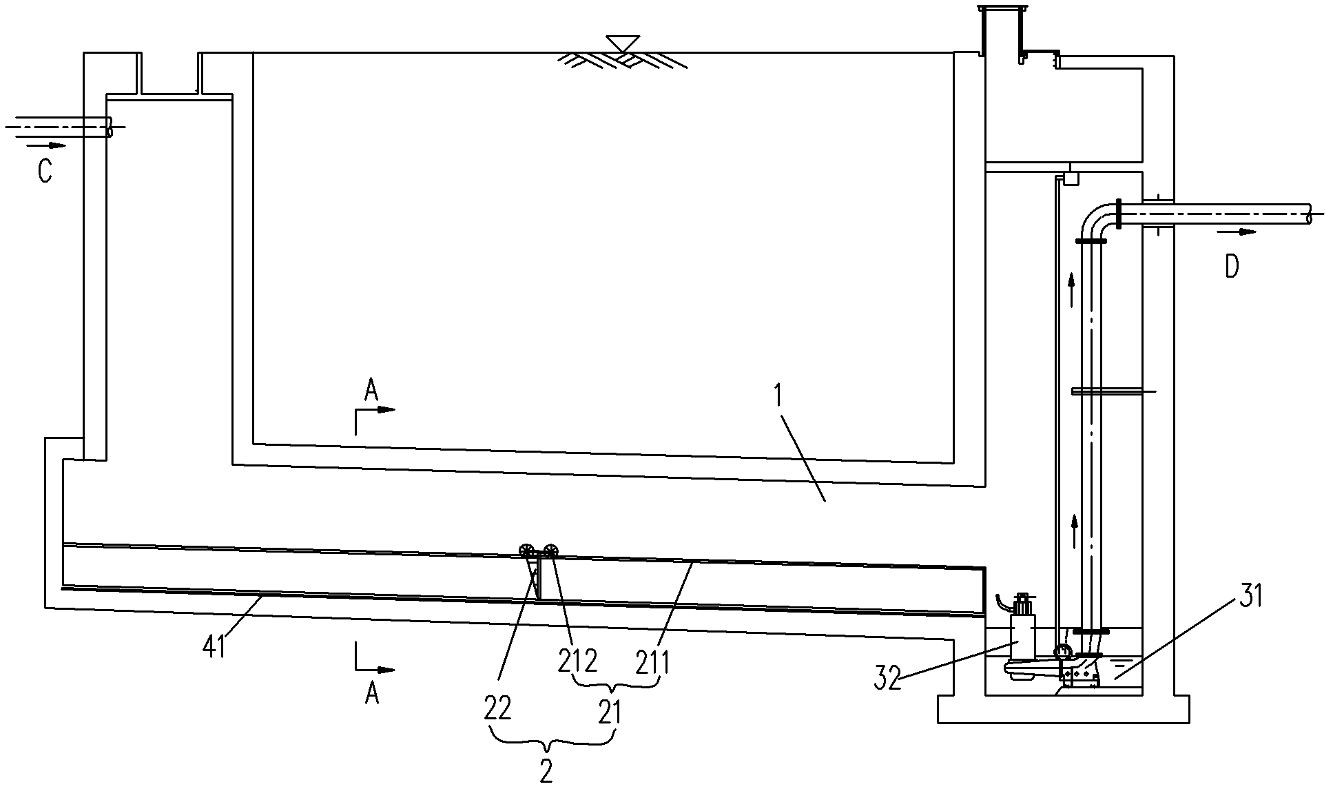
[0028] like figure 1 As shown in the regulation and storage pipe culvert 1 located deep in the ground, the inflow sewage flows into the regulation and storage pipe culvert 1 from point C, after regulation and storage, it is discharged from point D and enters the sewage pipe network. During this process, the sludge will settle at the bottom of the regulation and storage pipe culvert 1 .

[0029] The automatic desilting system of the underground regulating and storage pipe culvert of the present invention is used to clean up the silt, and mainly includes a slidable desilting device 2 and an aeration system arranged in the regulating and storing pipe culvert 1 1 The silt discharge tank 31 and the sewage pump 32 at the end.

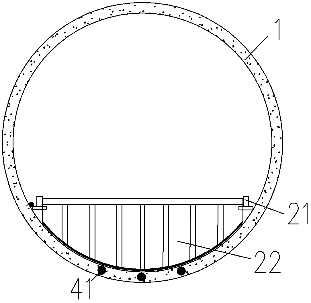
[0030] The desilting device 2 includes a sliding component 21 that can be displaced in the regulation and storage pipe culvert 1 , and a fender 22 fixed to the sliding component 21 .

[0031] Specifically, in this embodiment, the sliding assembly 21 include...

Embodiment 2

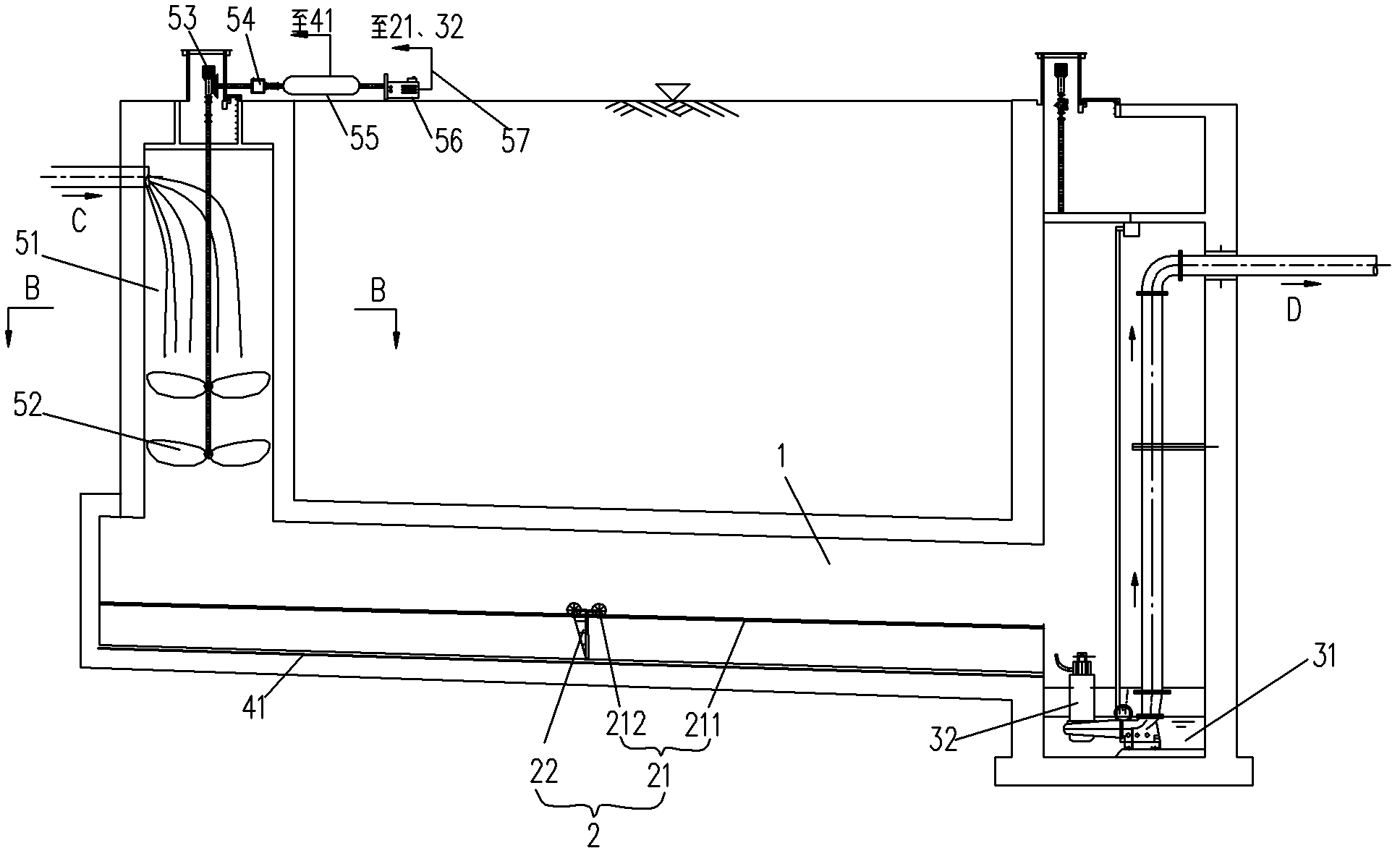
[0040] like image 3 , Figure 4 As shown, this embodiment is a further optimization of Embodiment 1. On the basis of the dredging device and the aeration system, a drop water energy storage device is added. The falling water energy storage device mainly includes a one-stage impeller 52 arranged at the bottom of the falling water shaft 51 (in different embodiments, according to different parameters such as head drop and inflow flow, multi-stage impellers can be set to meet energy dissipation requirements). The impeller 52 mainly includes a transmission rod 521 and an impeller 522, which are used to eliminate the potential energy generated by the free fall of rainwater and sewage from a large height, and convert the potential energy into kinetic energy.

[0041] The power output end of the impeller 52 is connected to the power input end of an air compressor 54 via a set of speed change gears 53 , and the air compressor 54 communicates with a compressed air storage tank 55 . T...


PUM


Abstract

The invention discloses an automatic dredging system for a storage-capacity-regulating pipe culvert. The system comprises a dredging device, wherein the dredging device can slide in the storage-capacity-regulating pipe culvert, wherein the tail end of the storage-capacity-regulating pipe culvert is provided with a silting discharging pool and a sewage pump; the automatic dredging system comprises an aeration system which comprises an exhaust pipe arranged at the bottom of the storage-capacity-regulating pipe culvert; and a plurality of aeration holes are formed on the lower side of the exhaust pipe. The automatic dredging system disclosed by the invention comprises a dropping water energy storage device. The automatic dredging system disclosed by the invention has the beneficial effects of simple structure, energy conservation, high automaticity, good dredging effects and the like.

Description

technical field [0001] The invention relates to the technical field of environmental protection, in particular to an automatic dredging system for underground regulation and storage pipes and culverts used for urban flood control. Background technique [0002] Due to the lag in the planning and construction of urban flood control and drainage systems in China, the problem of waterlogging in the rainy season is common in large and medium-sized cities in my country. When the waterlogging phenomenon caused by short-term heavy rainfall occurs, the surface runoff carries a large amount of pollutants into the urban water body, resulting in serious pollution of the water quality, bringing huge economic losses and serious ecological damage to the city. [0003] In order to solve the problem of urban waterlogging, the usual idea is to expand or build new drainage pipe networks and rainwater treatment plants. However, restricted by many factors such as project land, roads, buildings ...

Claims


Application Information

Patent Timeline
Patent Type & Authority Applications(China)
IPC IPC(8): E03F7/10E03F5/26F03G7/00
Inventor 贾仁勇张善发
Owner SHANGHAI URBAN CONSTR DESIGN RES INST GRP CO LTD
Why Eureka
Try Eureka