

Detecting system and detecting method for unbalanced loading of transportation vehicles
A technology for transporting vehicles and detection systems, applied in measuring devices, instruments, weighing and other directions, can solve problems such as inability to detect or monitor, and achieve the effect of improving accuracy, high reliability and wide application
- Summary
- Abstract
- Description
- Claims
- Application Information
AI Technical Summary
Problems solved by technology
Method used
Image

Examples
Embodiment Construction
[0025] The present invention takes 16-bit F90F340 series single-chip microcomputer as the core and high-precision digital output displacement sensor as the detection element. The system calculates and displays the corresponding unbalanced load according to the collected multi-channel displacement information.
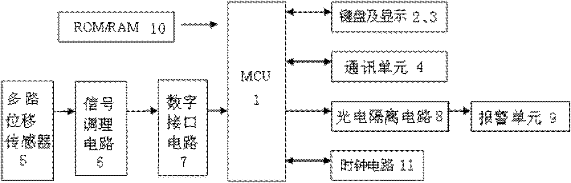
[0026] A vehicle load deviation detection system for transport vehicles, such as figure 1 As shown, it includes MCU1 (MB90F340 series microcontroller), keyboard 2, display 3, communication unit 4, multi-channel displacement sensor 5, signal conditioning circuit 6, digital interface circuit 7, photoelectric isolation circuit 8, alarm unit 9, ROM / RAM 10 and clock circuit 11. The system has a standard RS485 communication interface, and cooperates with the host computer to upload partial load information for subsequent work such as statistics and analysis.
[0027] MCU1 and its peripheral components, as well as the corresponding detection, judgment, control and other progr...
PUM
 Abstract
Description
Claims
Application Information