Variable frequency superconducting microstrip line resonator

A superconducting resonator and microstrip line technology, applied in the microwave field, can solve the problems of large design error, large filter insertion loss, slow frequency conversion response, etc., and achieves a large number of variable frequency points, accurate frequency control, and frequency conversion range. big effect

Active Publication Date: 2012-06-13
TSINGHUA UNIV
View PDF7 Cites 2 Cited by
  • Summary
  • Abstract
  • Description
  • Claims
  • Application Information

AI Technical Summary

Problems solved by technology

At present, there are two main implementation methods of variable frequency superconducting filters that have been published: one is to suspend a dielectric sheet above the superconducting microstrip line resonator, and change the suspension height of the dielectric sheet by mechanical movement, thereby changing the superconducting filter. The difficulty in realizing the resonant frequency of the resonator is that it is difficult to realize a micro-mechanical control device that requires extremely high precision and works at low temperature. The disadvantage is that the frequency conversion response is slo...

Method used


Image

  • Variable frequency superconducting microstrip line resonator
  • Variable frequency superconducting microstrip line resonator
  • Variable frequency superconducting microstrip line resonator

Examples


no. 1 example

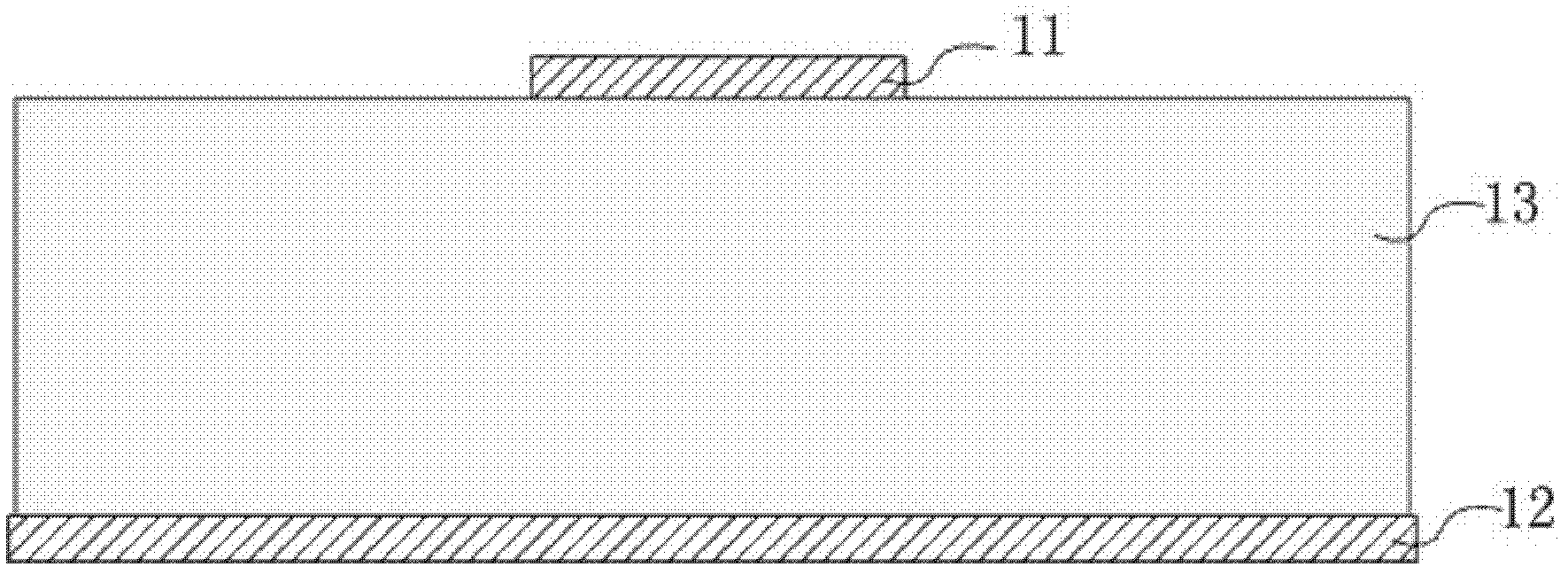
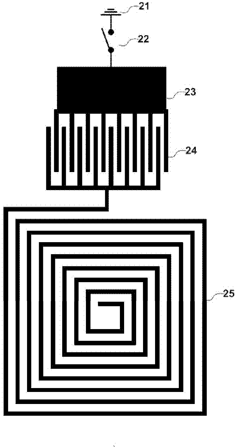
[0045] refer to figure 1 , this embodiment includes an upper superconducting resonator structure, a lower superconducting thin film, and a dielectric substrate between the upper and lower superconductors. The upper layer superconducting resonator structure of the present embodiment is as shown in Figure 2, comprises a continuous single spiral main strip line 25 (using a continuous microstrip line, this microstrip line is a superconducting microstrip line), the main strip The belt line is composed of eight circles in the counterclockwise direction from the outside to the inside. The coils are all rectangular coils. The outer contour of the outermost coil is 8.26mm long, 8.48mm wide, and the line width is 0.16mm. The circles are equally spaced with a pitch of 0.32mm. The outer port of the main strip line and an external microstrip line 23 form an interdigital coupling structure 24, the interdigital length is 2.4mm, the width is 0.16mm, the number of interdigital roots is 8, the...

no. 2 example

[0049] refer to figure 1 , this embodiment includes an upper superconducting resonator structure, a lower superconducting thin film, and a dielectric substrate between the upper and lower superconductors. The upper superconducting resonator structure of this embodiment is as follows Figure 3a As shown, it includes a continuous single-helical main stripline 37 (using a continuous microstrip line, which is a superconducting microstrip line), and the main stripline circles eight times in a counterclockwise direction from the outside to the inside. Composition, the coils are all rectangular coils, the outer contour of the outermost coil is 8.26 mm long, 8.48 mm wide, and the line width is 0.16 mm, and the adjacent coils are equally spaced and the distance is 0.32 mm. The outer port of the main strip line and two external microstrip lines (using a continuous microstrip line, the microstrip line is a superconducting microstrip line) form interdigital coupling structures 35 and 36 ...

no. 3 example

[0053] refer to figure 1 , this embodiment includes an upper superconducting resonator structure, a lower superconducting thin film, and a dielectric substrate between the upper and lower superconductors. The upper superconducting resonator structure of this embodiment is as follows Figure 4 As shown, it includes a continuous anti-cis-helical main strip line 45 (using a continuous microstrip line, which is a superconducting microstrip line), and the main strip line surrounds from the outside to the inside along the counterclockwise direction Four circles, and then four circles clockwise. The coils are all rectangular coils. The outer contour of the outermost coil is 8mm long, 8mm wide, and the line width is 0.16mm. The adjacent coils are equally spaced and the spacing is 0.24. mm. The external port of the main strip line and the four external microstrip lines 43 form an interdigital coupling structure 44 . The finger length of the finger coupling structure 44 is 2.4mm, the...


PUM

PropertyMeasurementUnit
Line widthaaaaaaaaaa
Widthaaaaaaaaaa

Abstract

The invention relates to a variable frequency superconducting microstrip line resonator, which comprises an upper-layer superconducting resonator structure, a lower-layer superconducting thin film and a dielectric substrate positioned between the upper-layer superconducting resonator structure and the lower-layer superconducting thin film. The variable frequency superconducting microstrip line resonator is characterized in that: the upper-layer superconducting resonator structure comprises a continuous main strip line, one or more external microstrip lines and one or more switches; one or two ends of the main strip line form an interdigital coupled structure with the one or more external microstrip lines; the interdigital coupled structure is formed by intersecting the port comb crotch structure of the main strip line and the port comb crotch structure(s) of the one or more external microstrip lines, and the port comb crotch structures of the main strip line and the one or more external microstrip lines do not contact each other; the external microstrip lines are grounded through the switches; and the grounding state, off state or state combinations of the one or more external microstrip lines are controlled by the one or more switches to change the resonance frequency of the resonator. The variable frequency superconducting microstrip line resonator has the advantages of high quality factor, wide variable frequency range, a great number of variable frequency points and frequency control accuracy, is easily made, and can be used for designing and manufacturing high-performance variable frequency band-pass, band elimination, high-pass, low-pass and multi-band superconducting filters.

Description

technical field [0001] The invention belongs to the field of microwave technology, and relates to a frequency-variable superconducting microstrip line resonator. Background technique [0002] Since the surface resistance of superconducting materials in the microwave frequency range is two to three orders of magnitude lower than that of conventional metal materials, superconducting filters composed of superconducting microstrip line resonators have excellent filtering characteristics. The basic composition of the conductive microstrip line resonator includes an upper layer superconducting resonator structure 11, a lower layer superconducting film 12, and a dielectric substrate 13 between the upper and lower layers of superconductors, such as figure 1 shown. Wherein, both the upper resonator structure 11 and the lower conductor thin film are superconductors; the substrate can be made of magnesium oxide substrate, lanthanum aluminate substrate, sapphire and other materials. I...

Claims


Application Information

Patent Timeline
IPC IPC(8): H01P7/08
Inventor 魏斌应志军曹必松张晓平郭旭波李启荣冯骋
Owner TSINGHUA UNIV
Why Eureka
Try Eureka