
Spectral-domain optical coherence tomography imaging system based on Fresnel spectrometer

A technology of optical coherence tomography and imaging system, which is applied in the field of frequency domain optical coherence tomography system, can solve the problems affecting the imaging speed of imaging system and the deterioration of vertical resolution of spatial domain signals, so as to avoid the deterioration of longitudinal resolution , high flexibility, and the effect of avoiding aberrations

Active Publication Date: 2012-06-20
TSINGHUA UNIV
View PDF5 Cites 27 Cited by
  • Summary
  • Abstract
  • Description
  • Claims
  • Application Information

AI Technical Summary

Problems solved by technology

However, at this time, the frequency spectrum recorded on the linear array CCD is expanded according to approximately equally spaced wavelengths, and the Fourier transform requires the frequency spectrum to be evenly expanded according to the wave number, otherwise the longitudinal resolution of the spatial domain signal after the Fourier transform will be changed. Difference
The existing frequency-domain optical coherence tomography system also needs to do wavelength-wavenumber conversion and resampling data post-processing, which greatly affects the imaging speed of the imaging system

Method used


Image

  • Spectral-domain optical coherence tomography imaging system based on Fresnel spectrometer
  • Spectral-domain optical coherence tomography imaging system based on Fresnel spectrometer
  • Spectral-domain optical coherence tomography imaging system based on Fresnel spectrometer

Examples


Embodiment Construction

[0014] The present invention will be described in detail below in conjunction with the accompanying drawings and embodiments.

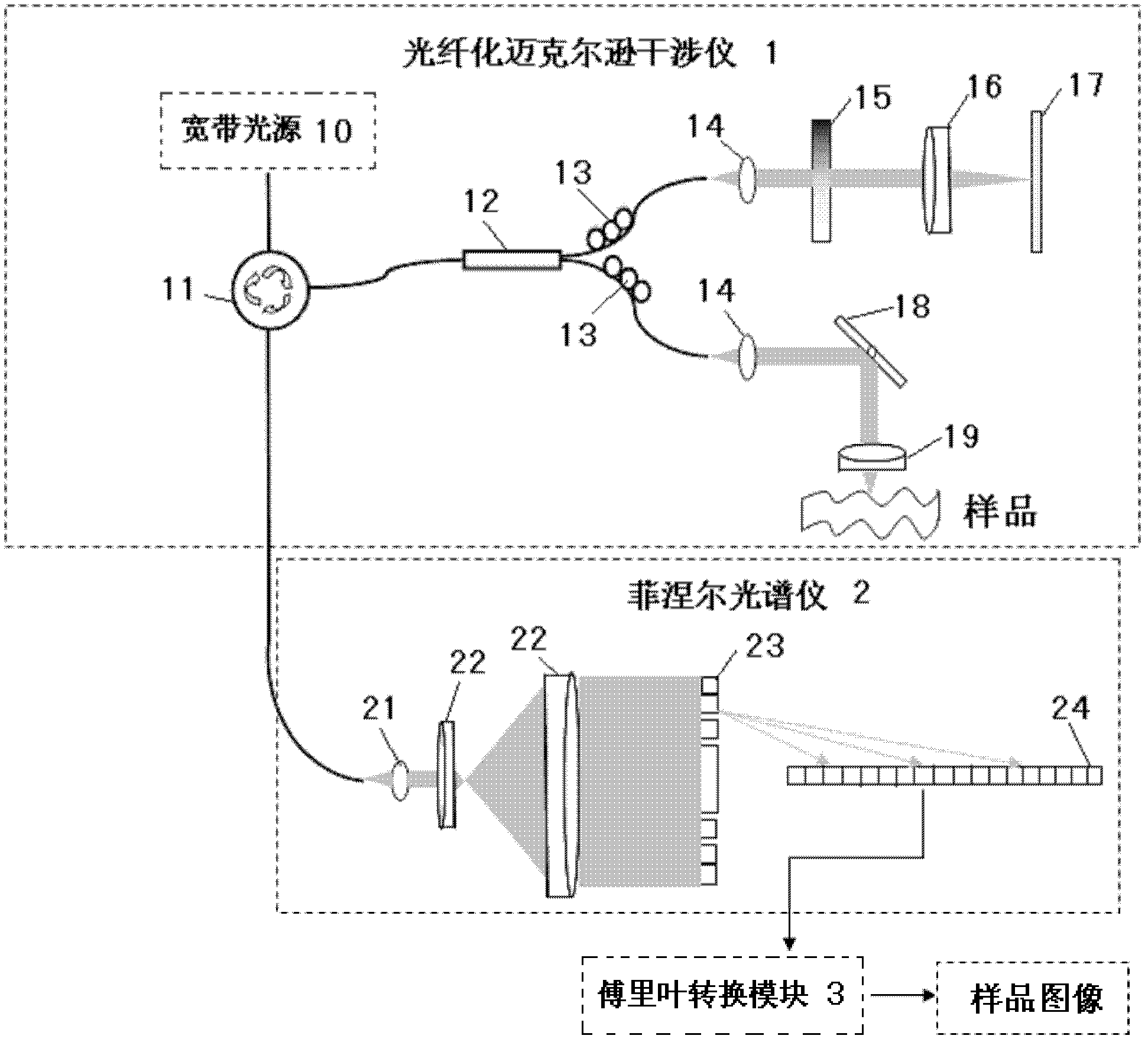
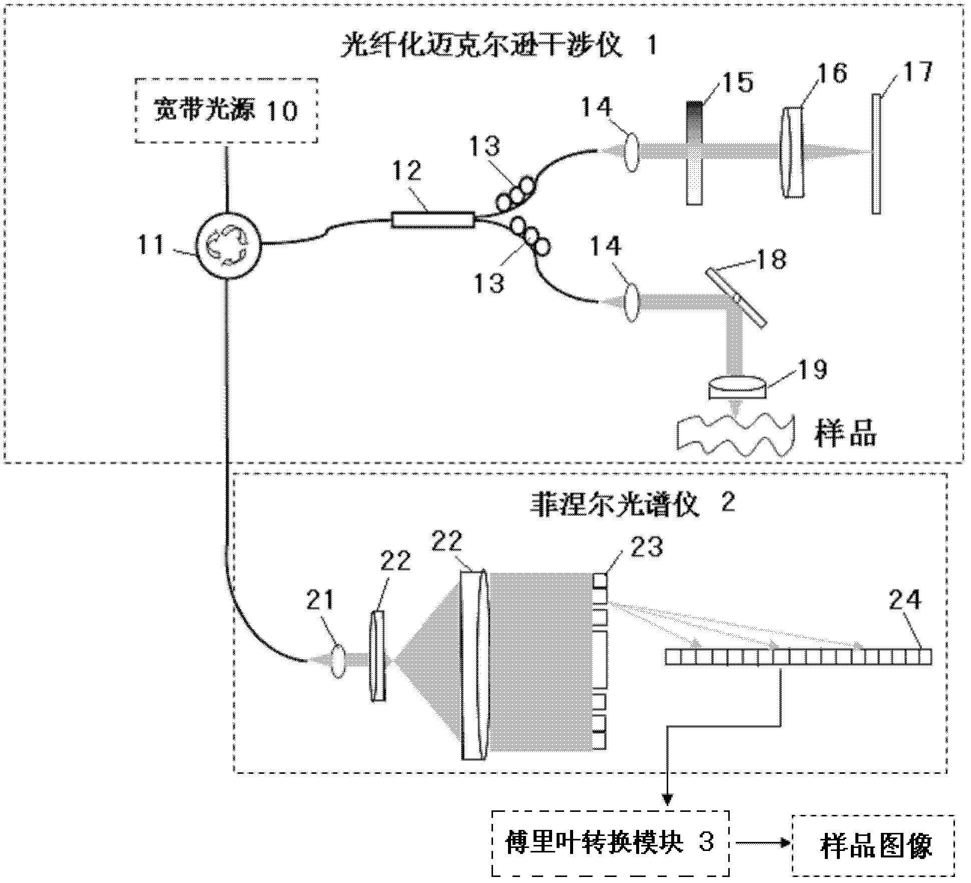
[0015] Such as figure 1 As shown, the present invention includes a fiber optic Michelson interferometer 1 , a Fresnel spectrometer 2 and a Fourier transform module (FFT) 3 .

[0016] The fiber optic Michelson interferometer 1 includes a broadband light source 10, the broadband light output by the broadband light source 10 is launched into a fiber circulator 11 through a single-mode fiber, and the broadband light is emitted in the fiber circulator 11 according to a fixed propagation path and passed through a single mode fiber is launched into a fiber coupler 12, and the fiber coupler 12 divides the broadband light into two beams according to the set splitting ratio. The broadband light is transmitted to a reference mirror 17 after passing through a collimating mirror 14 , an attenuating sheet 15 and a lens 16 . Another beam of broadband light is tran...


PUM


Abstract

The invention relates to a spectral-domain optical coherence tomography imaging system based on a Fresnel spectrometer, which is characterized by comprising a Michelson interferometer, the Fresnel spectrometer and a Fourier transformation module. The Michelson interferometer sends coherent light which is formed by superposing sample light returned from various layers of a sample with reference light into the Fresnel spectrometer, the coherent light is emitted onto a Fresnel zone plate parallelly through a collimating lens and an expanded beam lens respectively, and is expanded at the same interval according to the wave number and then projected to a linear array CCDs (charge coupled devices) by the Fresnel zone plate, frequency spectrum data of the coherent light are read by the linear array CCDs and sent to the Fourier transformation module, and then recovered into information of spatial position of the sample by means of discrete Fourier transformation through the Fourier transformation module. The spectral-domain optical coherence tomography imaging system based on the Fresnel spectrometer can be applied to not only spectral-domain optical coherence tomography imaging but also spectral analysis having requirements for wavelength-wave number conversion and resampling for imaging or detecting and required to be expanded uniformly according to the wave number, and especially can be applied to the biomedical imaging process.

Description

technical field [0001] The invention relates to a frequency-domain optical coherence tomography system, in particular to a frequency-domain optical coherence tomography system based on a Fresnel spectrometer. Background technique [0002] Optical coherence CT (Optical Coherence Tomography, OCT for short) technology has developed rapidly in the past ten years. This technology can perform tomographic imaging of biological tissues or human tissues, and its resolution is much higher than that of X-ray imaging and ultrasonic imaging. In particular, frequency-domain optical coherent CT (FD-OCT) technology not only has high-resolution tomographic imaging capabilities, but also has frequency-domain parallel reading capabilities, which can read a line of optical signals along a certain depth direction of the sample at one time. FD-OCT OCT technology also has the advantages of high sensitivity and great potential for high-speed imaging. [0003] In the fiber-based FD-OCT system, the ...

Claims


Application Information

Patent Timeline
IPC IPC(8): A61B5/00G01N21/45
Inventor 薛平张宁陈天元王成铭霍天成郑京镐
Owner TSINGHUA UNIV
Learn More