Method for manufacturing rotary optical fiber and rotary fiber winding device

A technology for rotating optical fibers and manufacturing methods, applied in manufacturing tools, glass manufacturing equipment, etc., can solve the problems of methods for reducing optical fiber birefringence, unsatisfactory mechanical properties, and difficult to achieve, and achieve good performance stability and use reliability. Easy to integrate applications, easy to handle the effects of use

Active Publication Date: 2012-06-20
武汉长盈通光电技术股份有限公司
View PDF9 Cites 15 Cited by
  • Summary
  • Abstract
  • Description
  • Claims
  • Application Information

AI Technical Summary

Problems solved by technology

[0006] There are some insurmountable problems in the circular polarization-maintaining optical fiber and its manufacturing process proposed in the above-mentioned patents: due to the use of an indefinite number of stress units in the optical fiber, the manufacturing process of the optical fiber preform, the drawing process and the subsequent optical fiber fusion processing process All are difficult, especially the manufacture of special-shaped preforms is difficult, and it is easy to burst and be scrapped
In addition, the method of reducing the birefringence of the optical fiber by rotating the optical fiber preform is also difficult to achieve in the actual optical fiber production process.
As pointed out in the patent application documents with publication number CN 1663922, since the part of the preform rod in the wire drawing furnace in

Method used


Image

  • Method for manufacturing rotary optical fiber and rotary fiber winding device
  • Method for manufacturing rotary optical fiber and rotary fiber winding device
  • Method for manufacturing rotary optical fiber and rotary fiber winding device

Examples


Embodiment 1~9

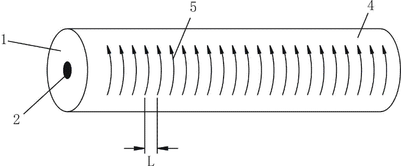
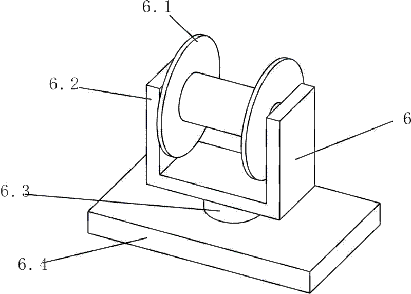
[0035] Select the G.652D type single-mode optical fiber preform, place the optical fiber preform 8 in the fiber drawing tower 7, and use the rotating fiber receiving device 6 provided by the present invention to draw an ultra-low birefringence single-mode optical fiber with rotation characteristics . Table 1 shows the birefringence of the manufactured single-mode optical fiber and the measured birefringence of each optical fiber under different drawing rotation parameters.

[0036] Table I

[0037] Example Optical fiber preform outer diameter (mm) Drawing speed of optical fiber preform (m / min / ) Horizontal rotation speed of fiber collection disc (r / min) Fiber cladding diameter after drawing (μm) Fiber rotation pitch L after drawing (mm) Tested fiber birefringence 1 15 50 1000 125 50 ~9.3×10 -7 2 15 10 800 125 12.5 ~5.1×10 -8 3 15 1 1000 125 1 ~6.2×10 -9 4 10 50 1000 125 50 ~8.6×10 -7 5 10 10 800 125 12.5...


PUM


Abstract

The invention discloses a method for manufacturing a rotary optical fiber. The method comprises a step of manufacturing an optical fiber preform and a step of drawing the optical fiber preform, wherein in the step of drawing the optical fiber preform, a lower end of the rotary optical fiber is rotated along an axial direction of the optical fiber under fiber drawing, and rotation formed in the optical fiber is fixed in the cooling process. The rotary fiber winding device for manufacturing the rotary optical fiber comprises a fiber winding disc arranged in a fiber drawing tower and under the drawn optical fiber, wherein the fiber winding disc has a shape of a spool and is used for rotating with a drawn optical fiber as a rotating axis so as to drive the lower end of the optical fiber to rotate and for rotating with a central shaft of the fiber winding disc as a rotating axis so as to wind the optical fiber. By an ultralow double refraction optical fiber product manufactured by the process and equipment, because the rotation is not generated or cured in a drawing furnace, influence of the rotation in a high-temperature melting state on optical and mechanical properties is avoided, the manufactured ultralow double refraction optical fiber has long-term reliability and stability, and the using requirement of a sensing optical fiber in a harsh environment is met.

Description

technical field [0001] The invention relates to a low birefringence optical fiber, in particular to a method for manufacturing a spun optical fiber and a spun fiber receiving device used in the method. Background technique [0002] Since the invention of optical fiber, it has been used in many technical fields, especially in the field of optical fiber communication. Various optical fiber products, including multimode optical fiber, single-mode optical fiber, dispersion compensation optical fiber, etc., have been widely used. In the field of sensing, optical fibers also play a unique role. Sensing optical fiber technology includes many aspects. Taking advantage of the sensitivity of optical fibers to different physical quantities, optical fiber sensing products for measuring different physical quantities have been developed, such as optical fiber sensors for temperature, humidity, pH value, refractive index, stress, and angular velocity. . [0003] It is well known that sin...

Claims


Application Information

Patent Timeline
IPC IPC(8): C03B37/025C03B37/03
Inventor 汪洪海皮亚斌
Owner 武汉长盈通光电技术股份有限公司
Why Eureka
Try Eureka