
Wall-type arranged two-stage burn-up air device

A burn-out wind and burn-out technology is applied in the combustion of multiple fuels, the combustion of lump fuel and liquid fuel, the combustion of lump fuel and gaseous fuel, etc. Fluctuation, low pulverized coal burnout, and high carbon content in fly ash can improve furnace mixing, strengthen turbulent mixing, and improve penetration.

Inactive Publication Date: 2012-06-20
HARBIN INST OF TECH
View PDF5 Cites 6 Cited by
  • Summary
  • Abstract
  • Description
  • Claims
  • Application Information

AI Technical Summary

Problems solved by technology

[0003] The purpose of the present invention is to solve the problem that the existing wall-type boilers cannot adapt to boiler load and coal quality fluctuations due to the arrangement of single-stage burnout air devices, resulting in low coal burnout, high carbon content in fly ash, and reduced To solve the problem of large amount of warm water, and then provide a two-stage overfire air device with wall arrangement

Method used


Image

  • Wall-type arranged two-stage burn-up air device
  • Wall-type arranged two-stage burn-up air device
  • Wall-type arranged two-stage burn-up air device

Examples


specific Embodiment approach 1

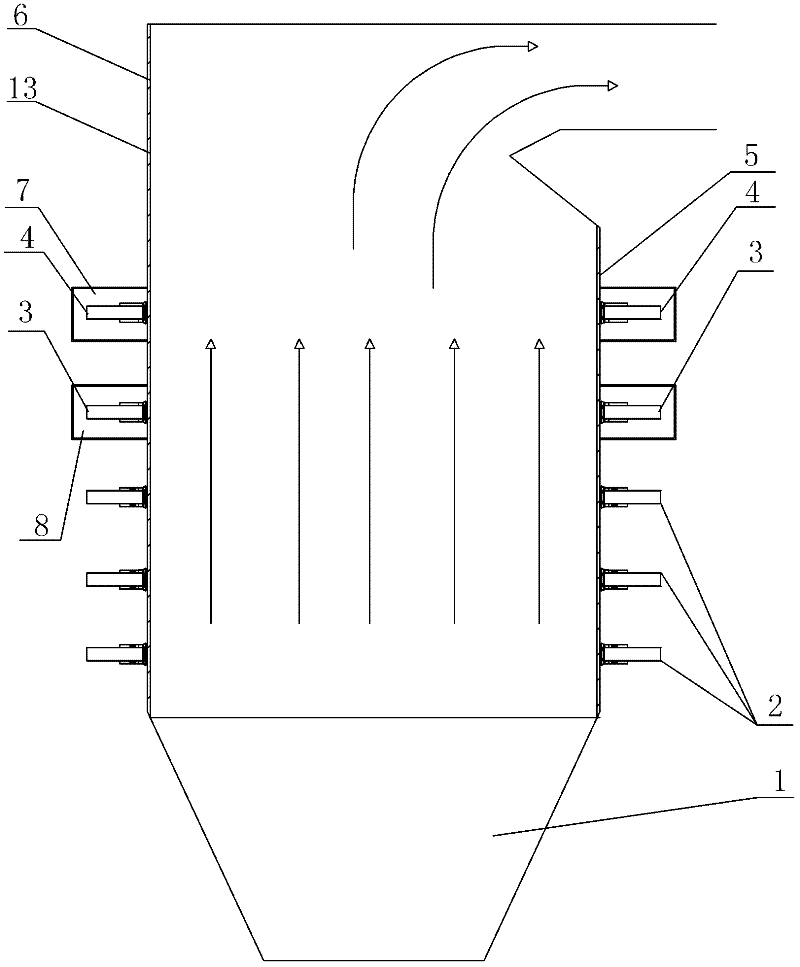
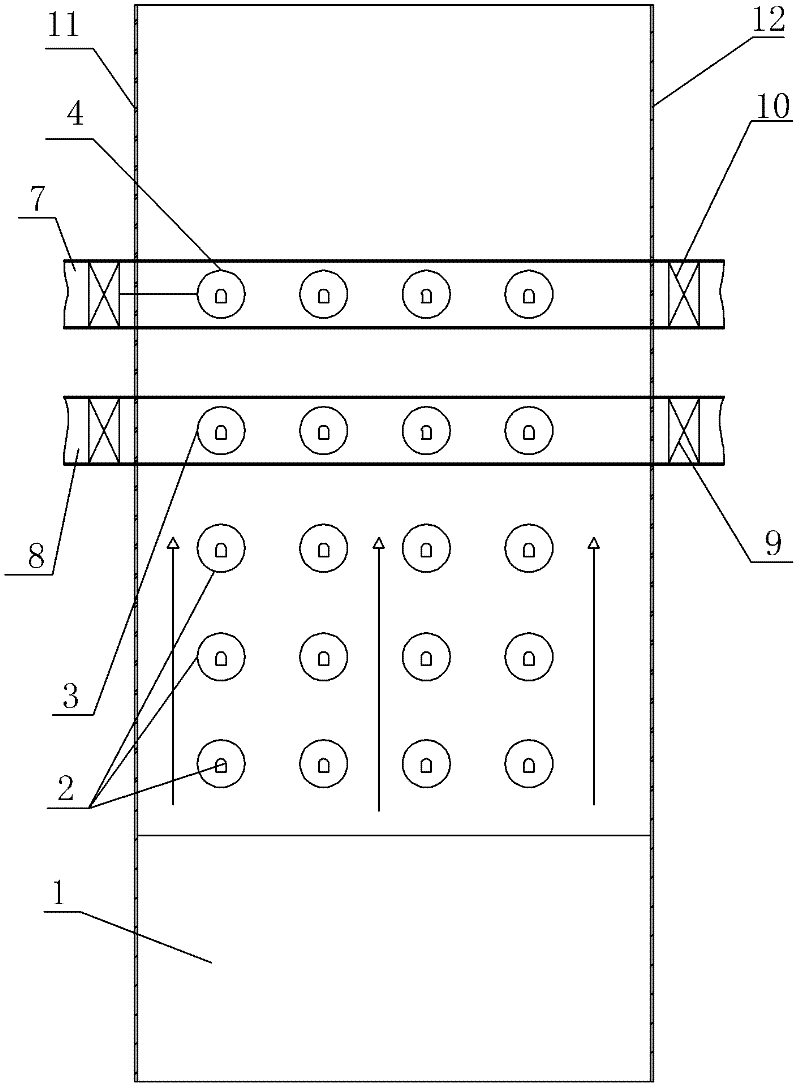
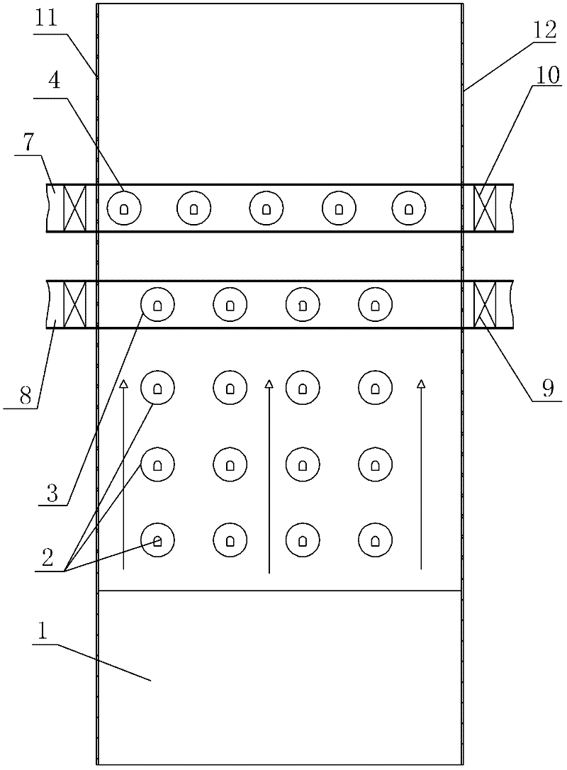
[0010] Specific implementation mode one: combine Figure 1 to Figure 7 Describe this embodiment, a wall-type two-stage overfire air device of this embodiment includes a cold ash hopper 1, a furnace wall 13 and a plurality of swirl burners 2, and the furnace wall 13 includes a rear wall 5. The front wall 6, the left wall 11 and the right wall 12. The device also includes multiple first-stage burn-off air 3, multiple second-stage burn-off air 4, multiple first-stage burn-off air bellows 8, multiple A second-stage overburning air wind box 7, a plurality of first-stage overburning air dampers 9 and a plurality of second-stage overburning air dampers 10, the lower end of the furnace wall 13 is connected to the upper end of the cold ash hopper 1, the described A plurality of swirl burners 2 are arranged on the wall 13 in multiple layers, a plurality of first-stage burn-off air 3 is arranged on the wall 13 and above the uppermost swirl burner 2, and a plurality of first-stage burners...

specific Embodiment approach 2

[0011] Specific implementation mode two: combination figure 1 and figure 2 To illustrate this embodiment, a plurality of swirl burners 2 described in this embodiment are arranged in multiple layers on the front wall 6 and the rear wall 5, and a plurality of first-stage overfire air 3 are symmetrically arranged on the front wall 6 and the rear wall 5 and above the uppermost swirl burner 2 , a plurality of second-stage overfire air 4 is symmetrically arranged on the front wall 6 and rear wall 5 and above the first-stage overfire air 3 . Such setting can more effectively improve the penetration of the overburning air, and can strengthen the turbulent mixing of the overburning air with the high-temperature flue gas and unburned coke in the furnace, improve the mixing of the furnace, better ensure the burnout rate, and effectively Control the carbon content of the fly ash and the amount of desuperheating water at a reasonable level to meet the design requirements. Others are the...

specific Embodiment approach 3

[0012] Specific implementation mode three: combination figure 2 To illustrate this embodiment, the arrangement of each layer of swirl burners 2 described in this embodiment is consistent with the arrangement of the first-stage overfire air 3 and the second-stage overfire air 4 . Such setting meets the design requirements. Others are the same as in the second embodiment.


PUM


Abstract

A wall-type arranged two-stage burn-up air device relates to a wall-type arranged burn-up air device which can solve the problems of low coal powder burn-up degree, high fly ash carbon content and high attemperation water flow for existing wall-type arranged boilers caused by the adoption of a single-stage burn-up air device arrangement mode that does not adapt boiler loads and coal quality fluctuation. The device comprises a plurality of first-stage burn-up air, a plurality of second-stage burn-up air, a plurality of first-stage burn-up air bellows, a plurality of second-stage burn-up air bellows, a plurality of first-stage burn-up air doors, and a plurality of second-stage burn-up air doors; a lower end of a hearth wall body is connected with an upper end of a cold ash hopper; the plurality of swirl burners are arranged on the wall body in a multilayer mode; the plurality of first-stage burn-up air are arranged on the wall body and are located above the swirl burner at the top layer; the plurality of second-stage burn-up air are arranged on the wall body and are located above the first-stage burn-up air; the plurality of first-stage burn-up air are disposed in the first-stage burn-up air bellows. The invention is applicable to boilers.

Description

technical field [0001] The invention relates to a wall-type overfire air device. Background technique [0002] 67% of my country's nitrogen oxide emissions come from coal combustion. Nitrogen oxides in the atmosphere include NO, NO 2 , N 2 O, N 2 o 3 , N 2 o 4 , N 2 o 5 etc., are usually collectively referred to as NOx. NOx will cause a series of environmental pollution problems, endanger human health, and destroy the ecological environment of the earth. Its harmfulness is specifically manifested as: (1) toxic effect on human body and plants, affecting the healthy development of organisms; (2) NOx generates photochemical smog to reduce visibility, and has strong toxic effect on human eyes, respiratory tract and lungs, and Can cause cancer; (3) The destructive effect of NOx on ozone indirectly harms the earth's organisms; (4) NOx is the main pollutant that forms acid rain and destroys the earth's ecological environment. With the improvement of environmental protect...

Claims


Application Information

Patent Timeline
IPC IPC(8): F23C7/02F23C5/08
Inventor 陈智超李争起遆曙光朱群益曾令艳李渊
Owner HARBIN INST OF TECH
Learn More