Collecting device of greenhouse gases released by lake and reservoir water bodies and analysis method of release rate

A technology for greenhouse gases and collection devices, which is applied to measurement devices, analytical materials, sampling devices, etc., can solve problems such as difficulty in collecting greenhouse gases, and achieve the effects of ensuring the contact area, reducing the impact, and reducing the weight of the device.

Inactive Publication Date: 2012-06-20
NANJING UNIV
View PDF5 Cites 16 Cited by
  • Summary
  • Abstract
  • Description
  • Claims
  • Application Information

AI Technical Summary

Problems solved by technology

[0008] Aiming at the problem of difficulty in collecting greenhouse gases at the water-air interface in the prior art, the present invention provides a device for collecting greenhouse gases released from lakes and reser

Method used


Image

  • Collecting device of greenhouse gases released by lake and reservoir water bodies and analysis method of release rate
  • Collecting device of greenhouse gases released by lake and reservoir water bodies and analysis method of release rate
  • Collecting device of greenhouse gases released by lake and reservoir water bodies and analysis method of release rate

Examples


Embodiment 1

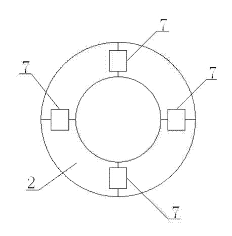
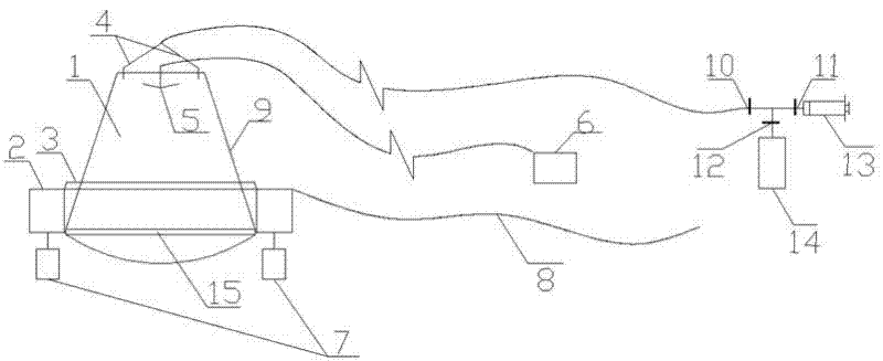
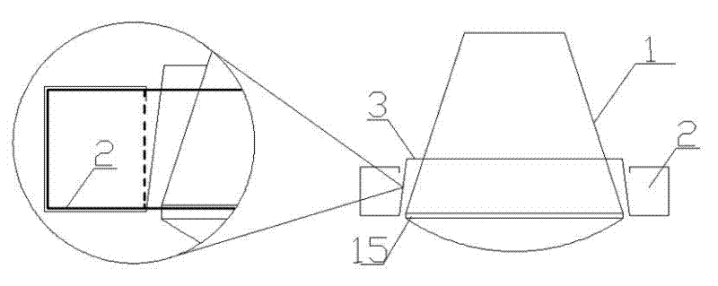
[0044] A collection device for releasing greenhouse gases from lake and reservoir water bodies of the present invention comprises a water gas collection system and a gas sample collection system; the water gas collection system is composed of a PVC barrel 1 and a life buoy 2, and the PVC barrel 1 Inverted in the life buoy 2, the mouth of the PVC barrel 1 coincides with the lower edge of the life buoy 2, the gas collection system includes a gas collection pipe 4, a three-way valve, a suction gas plastic syringe 13 and an aluminum foil vacuum bag 14. One end of the gas collection pipe 4 is connected to the top of the PVC barrel, and the other end of the gas collection pipe 4, the suction gas plastic syringe 13, and the aluminum foil vacuum bag 14 are respectively connected to the valve I10, valve II11, and valve III12 of the three-way valve. connected. The size and capacity of the suction plastic syringe and the aluminum foil vacuum bag are determined according to actual needs. ...

Embodiment 2

[0055] The difference of this embodiment compared to Example 1 is that a kind of release rate analysis method of lake and reservoir water releases greenhouse gases of the present invention, in step (C), the amount of gas extracted is 70ml; in step (E) The sampling interval is 15 minutes; in step (F), one point is sampled 8 times; in step (G), 13 points are taken for gas collection.

Embodiment 3

[0057] The difference of this embodiment compared to Example 1 is that a kind of release rate analysis method of lake and reservoir water releases greenhouse gases of the present invention, in step (C), the amount of gas extracted is 80ml; in step (E) The sampling interval is 20 minutes; in step (F), one point is sampled 9 times; in step (G), 15 points are taken for gas collection.


PUM


Abstract

The invention belongs to the field of laboratory instrument equipment, and discloses a device for collecting greenhouse gases released by lake and reservoir water bodies and an analysis method of release rate. The device comprises an overwater gas collecting system and a gas sample collecting system, wherein the overwater gas collecting system is composed of a PVC (Polyvinyl Chloride) and a buoy; the PVC barrel is inverted in the buoy, and the barrel port of the PVC barrel is coincided with the lower edge of the buoy; the gas collecting system comprises a gas collecting pipe, a tee valve, a gas sucking plastic needle cylinder and an aluminum foil vacuum bag; one end of the gas collecting pipe is communicated with the top of the PVC barrel; and the other end of the gas collecting pipe, the gas sucking plastic needle cylinder and the aluminum foil vacuum bag are respectively communicated with a valve I, a valve II and a valve III of the tee valve. By adopting the device disclosed by the invention, the problem that the greenhouse gases in the lake and reservoir are difficultly collected is solved; and the device is simple and convenient in structure, easy to operate and is high in experiment precision.

Description

technical field [0001] The invention belongs to the field of experimental instruments and equipment, and relates to a method for collecting lakes and reservoirs to release greenhouse gases (CO 2 、CH 4 , N 2 O, etc.) device and release rate analysis method, in particular to a collection device that can be used for greenhouse gas release from lakes and reservoir water surfaces, and a method for analyzing gas release rate. Background technique [0002] In recent years, the global climate has shown a trend of heretical changes, which will bring devastating damage to human beings and ecosystems, including melting glaciers, rising sea levels, and increased drought and flood disasters. Atmospheric greenhouse gases (CO 2 、CH 4 , N 2 O, etc.) is the decisive factor leading to climate warming. Greenhouse gases absorb long-wave radiation from sunlight and reflect it back to Earth, thereby reducing the net emission of energy into outer space, leading to warming of the atmosphere a...

Claims


Application Information

Patent Timeline
IPC IPC(8): G01N1/24G01N30/02
Inventor 孙成祝栋林何欢杨绍贵梁峰
Owner NANJING UNIV
Why Eureka
Try Eureka