Multi-shaft cascaded mechanical drilling machine

A cascading and mechanical technology, applied in the direction of metal processing machinery parts, boring/drilling, drilling/drilling equipment, etc. Problems such as the large span of the coupling beam achieve the effects of easy assembly, reduced deformation, and reduced overall volume

Active Publication Date: 2012-06-27
HANS CNC SCI & TECH
View PDF9 Cites 6 Cited by
  • Summary
  • Abstract
  • Description
  • Claims
  • Application Information

AI Technical Summary

Problems solved by technology

However, the current multi-axis cascading mechanical drilling rig has the following problems: 1. The volume of the machine is large; 2. The span of the cascade shaft beam is large (nearly 4 meters), and the deformation is large; 3. The length of the machine table The direction size is also relatively large (more than 3 meters), resulting in a large error in the swing angle of the guide rail running direction; 4. The a

Method used


Image

  • Multi-shaft cascaded mechanical drilling machine
  • Multi-shaft cascaded mechanical drilling machine
  • Multi-shaft cascaded mechanical drilling machine

Examples


Embodiment Construction

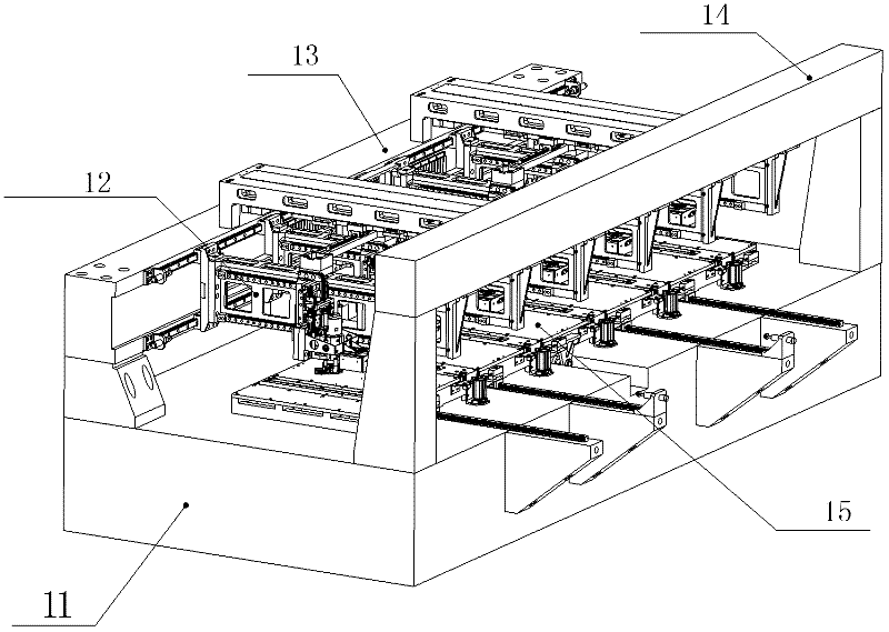
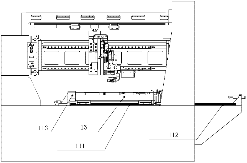
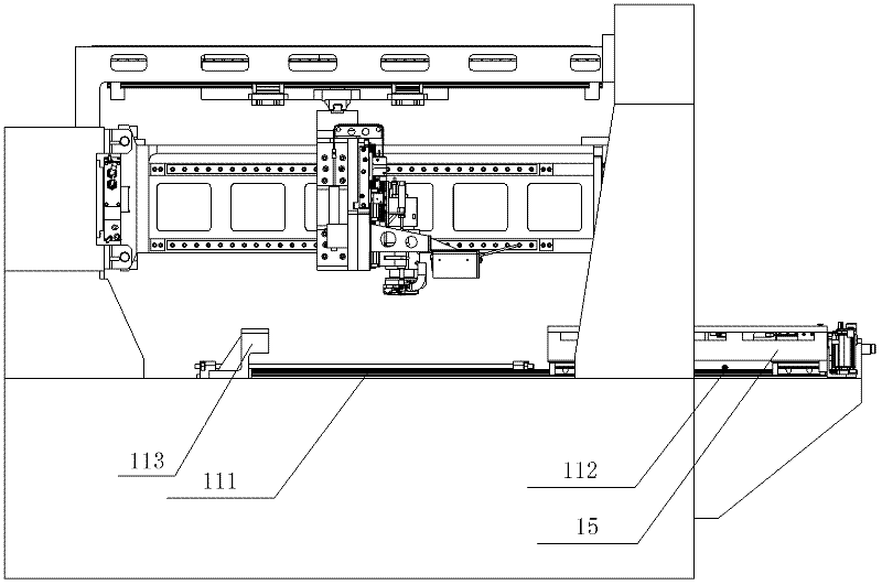
[0040] The overall structure of the multi-axis cascade mechanical drilling rig in the preferred embodiment of the present invention is as follows: figure 1 , Figure 4 and Figure 5 As shown, the bed 11 is included, and the main beam 13 and the auxiliary beam 14 parallel to each other are fixedly arranged on the bed 11, and there are at least three connecting support points between the main beam 13 and the bed 11; A workbench 15 is provided on which work components for completing the assembly of the circuit board are arranged; between the main crossbeam 13 and the auxiliary crossbeam 14, there are three suspensions for driving the work components to move in the X direction, the Y direction and the Z direction. Coordinate axis motion assembly 12; the three coordinate axis motion assembly 12 includes a plurality of working axes and is used to drive the working axis group 51 of the working assembly, and also includes an X coordinate driving component for controlling the movement...


PUM


Abstract

The invention relates to a multi-shaft cascaded mechanical drilling machine, comprising a machine body. A main beam and an auxiliary beam are mutually parallel and fixedly arranged on the machine body. At least three connection supporting points are arranged between the main beam and the machine body. An operating platform is further fixedly arranged on the machine body and is provided with a working component for assembling a circuit board. A three-coordinate axis movement component for driving the working component to move in an X direction, a Y direction and a Z direction is hung between the main beam and the auxiliary beam. The three-coordinate axis movement component comprises a working shaft group, an X coordinate driving component and a Y coordinate driving component, wherein the working shaft group consists of a plurality of working shafts and is used for driving the working component; the X coordinate driving component is used for controlling the working shaft group movement in the X direction; and the Y coordinate driving component is used for controlling the working shaft group movement in the Y direction. Each working shaft in the working shaft group is respectively provided with a Z coordinate driving device for driving the working component movement in the Z direction. The X coordinate driving component, the Y coordinate driving component and the working shaft group are connected in a framework manner.

Description

technical field [0001] The invention relates to the technical field of mechanical processing, and more specifically, relates to a multi-axis cascaded mechanical drilling machine. Background technique [0002] Mechanical drilling rig is one of the main processing machines in the Printed Circuit Board (PCB) industry. Its main performance evaluation indicators are: efficiency, precision and processing range. In order to improve the processing efficiency of mechanical drilling rigs, multi-axis cascading structures are generally used. However, the current multi-axis cascading mechanical drilling rig has the following problems: 1. The volume of the machine is large; 2. The span of the cascade shaft beam is large (nearly 4 meters), and the deformation is large; 3. The length of the machine table The direction size is also relatively large (more than 3 meters), resulting in a large swing angle error in the direction of guide rail running; 4. The multi-axis cascade structure is diff...

Claims


Application Information

Patent Timeline
IPC IPC(8): B23B41/02B23B47/20B23Q1/01
Inventor 宋福民廉成李宁高云峰
Owner HANS CNC SCI & TECH
Why Eureka
Try Eureka