
A laser processing mechanism with a shank

A laser processing and laser processing head technology, applied in metal processing equipment, laser welding equipment, manufacturing tools, etc., can solve the problems of parts processing range, limited processing accuracy, no large-scale equipment, limited application range, etc. The effect of saving processing steps, making good use of current resources and improving process flexibility

Active Publication Date: 2015-08-19
武汉飞能达激光技术有限公司
View PDF11 Cites 0 Cited by
  • Summary
  • Abstract
  • Description
  • Claims
  • Application Information

AI Technical Summary

Problems solved by technology

[0005] 1. The processing range and processing accuracy of parts are limited: large-format processing is mainly limited to plane laser cutting machines
Three-dimensional laser processing machine tools, especially high-precision three-dimensional laser processing machine tools, have a relatively small size range, and the current application range in industry is limited
However, at present, there is no large-scale equipment integrated with mechanical processing / laser processing functions combined with conventional multi-axis linkage CNC machine tools such as gantry milling at home and abroad.

Method used


Image

  • A laser processing mechanism with a shank
  • A laser processing mechanism with a shank
  • A laser processing mechanism with a shank

Examples


Embodiment Construction

[0023] The present invention is described in more detail below by means of examples, but the following examples are only illustrative, and the protection scope of the present invention is not limited by these examples.

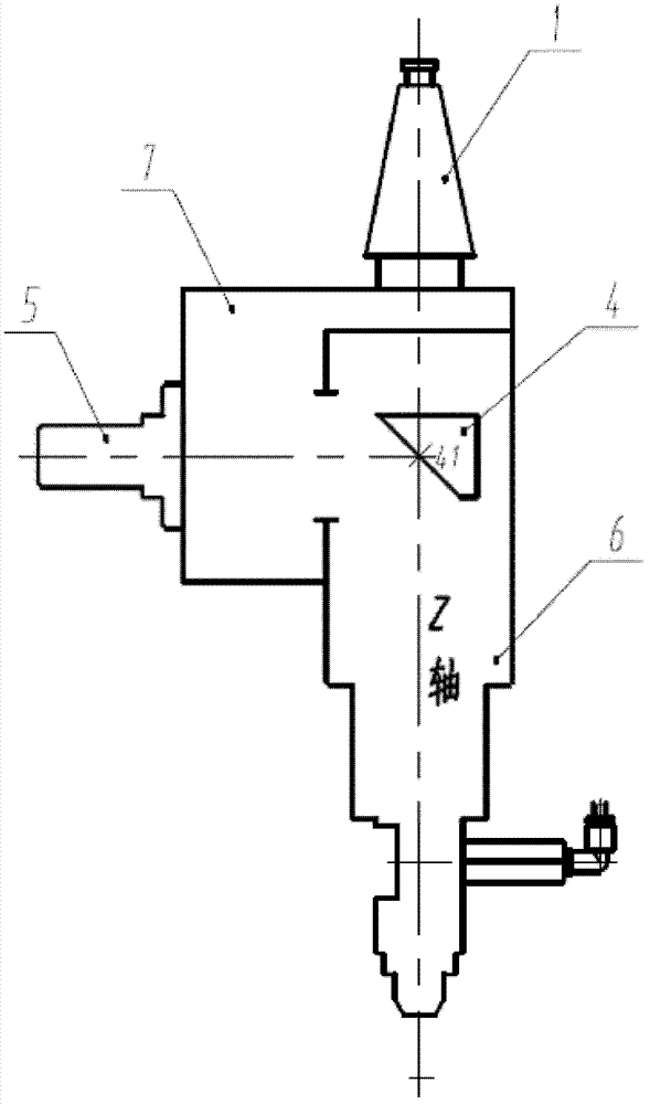
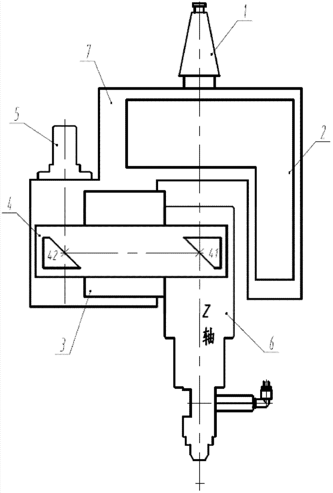
[0024] Such as figure 1 As shown, the laser processing mechanism with a handle of the present invention includes: a handle 1 , a light guide system 4 , an optical fiber connection seat 5 , a laser processing head 6 and a frame 7 .

[0025] The tool handle 1 is fixedly installed on the upper part of the frame 7, and is used to connect the main shaft of the multi-axis linkage CNC machine tool with the laser processing mechanism, so as to realize the combination of the multi-axis linkage CNC machine tool and the laser processing mechanism.

[0026] The optical fiber connection seat 5 is fixedly installed on one side of the frame 7, and is used for installing the transmission optical fiber joint, and the laser beam emitted by the laser is introduced into the laser...


PUM


Abstract

The invention discloses a laser processing mechanism with a cutter handle. The structure of the laser processing mechanism with the cutter handle is that the cutter handle is installed at the upper portion of a frame and used for connecting a spindle of a multiaxial linkage numerical control machine and the laser processing mechanism, an optical fiber connection base is fixedly installed on one side of the frame and used for installing a transmission optical fiber connector and transmitting a laser beam emitted by a laser device into the laser processing mechanism, a laser processing head is installed at the lower portion of the frame, and a laser leading system is installed in the laser processing head and used for leading the laser beam out of the laser processing head onto a workpiece to be processed. A rotary mechanism or / and swinging mechanism can be additionally arranged on the laser processing mechanism. The laser processing mechanism is provided with the cutter handle with a standard structure so that the combination of the laser processing mechanism and the conventional multiaxial linkage numerical control machine is simple and easy, process flexibility is greatly improved, and the multiaxial linkage numerical control machine can be conveniently and quickly transformed into a multifunctional machine with a laser processing function.

Description

technical field [0001] The invention belongs to the field of laser processing applications, in particular to a laser processing mechanism with a handle. Background technique [0002] Laser processing is a non-contact processing method that is increasingly widely used. It uses a high-power-density laser beam to act on the workpiece to heat, melt or vaporize it to achieve cutting, welding, hardening, cladding, deformation or marking. Line and other processing purposes. A complete laser processing system includes a control system, a laser, a light guide system, a multi-axis linkage CNC machine tool or robot, and a laser processing head. [0003] Existing laser processing machine tools are combined systems of lasers and multi-axis linkage CNC machine tools or robots, in which lasers are generally CO 2 lasers, Nd:YAG lasers and fiber lasers. Previously, most laser processing machine tools used CO 2 Laser, because its light guide system must be transmitted by the so-called "ha...

Claims


Application Information

Patent Timeline
Patent Type & Authority Patents(China)
IPC IPC(8): B23K26/00B23K26/08
Inventor 曾晓雁杜敏李重洋胡乾午蒋明段军高明李祥友
Owner 武汉飞能达激光技术有限公司
Learn More