Knife holder of machine tool

A tool holder and machine tool technology, which is applied in the new structure field of machine tool holders, can solve the problems of complex manufacturing and assembly process, large overturning moment of cutting force, complex tool holder structure, etc., and achieve simplification of assembly process, reduction of overturning moment, tool The effect of simple frame structure

Inactive Publication Date: 2012-06-27
重庆格恩格机床有限公司
View PDF9 Cites 12 Cited by
  • Summary
  • Abstract
  • Description
  • Claims
  • Application Information

AI Technical Summary

Problems solved by technology

[0003] The tool post of the traditional gear hobbing machine is installed on the sliding guide rail of the main shaft slide plate seat, and the main shaft slide plate seat is installed on the sliding guide rail of the tool post housing. The distance between the positioning and mounting surface of the tool holder shell is too large, so that the overturning moment caused by the cutting force is too large, and the hobbing accuracy is low; secondly, the structure of the tool holder is complicated and the combination accuracy is poor
At the same time, the tool shifting mechanism of the traditional gear hobbing machine is arranged between the tool holder shell and the spindle skateboard seat, and the manufacturing and assembly process is complicated; the spindle skateboard seat is a concave curved surface, which has problems such as difficulty in chip removal
[0004] To sum up, the tool post of the traditional gear hobbing machine has defects such as complex structure, low combination accuracy, poor workmanship, difficult chip removal, large overturning torque during cutting, and low machining accuracy.

Method used


Image

  • Knife holder of machine tool
  • Knife holder of machine tool
  • Knife holder of machine tool

Examples


Embodiment Construction

[0015] The present invention will be described in detail below through specific examples.

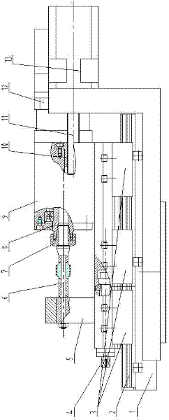
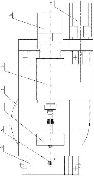
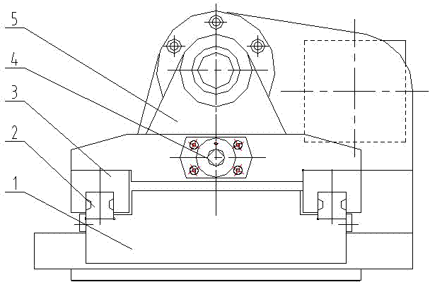
[0016] Such as Figure 1 to Figure 3 As shown, a machine tool holder is used for a gear hobbing machine or a worm wheel grinding machine, and has a tool holder housing 1, a bracket 5, a main shaft 8, a main shaft slide plate seat 9, a main shaft driving system 12, a knife shifting motor 13 and is installed on The tool mandrel 6 between the bracket 5 and the main shaft 8 is provided with a sliding guide rail 2 on the tool post housing 1, and the lower ends of the bracket 5 and the main shaft skateboard seat 9 are flat structures, and the bracket 5 and the main shaft skateboard seat 9 are respectively The slider 3 is supported on the sliding guide rail 2 , and the bracket locking mechanism 4 is installed between the bracket 5 and the main shaft skateboard seat 9 . That is to say, the bracket 5 and the main shaft skateboard seat 9 are supported on the same sliding guide rail pair on the t...


PUM


Abstract

The invention provides a knife holder of a machine tool. The knife holder comprises a knife holder housing (1), a bracket (5), a spindle (8), a spindle sliding plate seat (9), a spindle driving system (12), a knife shifting motor (13), and a knife core shaft (6) mounted between the bracket (5) and the spindle (8); a sliding guide rail (2) is only arranged on the knife holder housing (1); flat plate structures are arranged at the lower ends of the bracket (5) and the spindle sliding plate seat (9); the bracket (5) and the spindle sliding plate seat (9) are respectively supported on the sliding guide rail (2) through sliding blocks (3); a bracket locking mechanism (4) is mounted between the bracket (5) and the spindle sliding plate seat (9); and the knife shifting motor (13), a nut (10) and a lead screw (11) are arranged on the left side or the right side of the spindle sliding plate seat (9). By adopting the technical scheme provided by the invention, the knife holder used on a gear hobbing machine or a worm wheel gear grinding machine has the advantages of simple structure, high rigidity, high assembly manufacturability and high assembly precision, can effectively improve the processing precision of parts, and is suitable for dry / wet cutting processing.

Description

technical field [0001] The invention relates to a novel structure of a tool holder of a machine tool, in particular to a tool holder of a machine tool which can be used for a gear hobbing machine and a worm grinding wheel gear grinding machine. Background technique [0002] Gears are a key basic component and are widely used in various types of machinery. The gear hobbing machine is the main gear processing machine tool used most in gear processing, and the tool holder is one of the two important components of the gear hobbing machine. With the development of science and technology, higher and higher requirements are put forward for gear processing machine tools, mainly in the aspects of numerical control, high efficiency, high precision and environmental protection processing. [0003] The tool post of the traditional gear hobbing machine is installed on the sliding guide rail of the main shaft slide plate seat, and the main shaft slide plate seat is installed on the slidi...

Claims


Application Information

Patent Timeline
Patent Type & Authority Applications(China)
IPC IPC(8): B23Q5/40B23F23/00
Inventor 张广铭张庆益刘振兴张华欧
Owner 重庆格恩格机床有限公司
Why Eureka
Try Eureka