Method for manufacturing doped optical fibre preform by MCVD (modified chemical vapour deposition)

A technology for doping optical fibers and preforms, which is applied to manufacturing tools, glass manufacturing equipment, etc., can solve the problems of large consumption of rare earth solution and longitudinal unevenness of rare earth doping, saving time, uniform distribution, and reducing manufacturing costs. Effect

Active Publication Date: 2012-06-27
HANGZHOU FUTONG COMM TECH CO LTD
View PDF5 Cites 28 Cited by
  • Summary
  • Abstract
  • Description
  • Claims
  • Application Information

AI Technical Summary

Problems solved by technology

[0006] The technical problem to be solved and the technical task proposed by the present invention are to overcome the problems of large consumption of rare earth solution and uneven longitudinal doping of rare earth in

Method used


Image

  • Method for manufacturing doped optical fibre preform by MCVD (modified chemical vapour deposition)
  • Method for manufacturing doped optical fibre preform by MCVD (modified chemical vapour deposition)
  • Method for manufacturing doped optical fibre preform by MCVD (modified chemical vapour deposition)

Examples


Embodiment 1

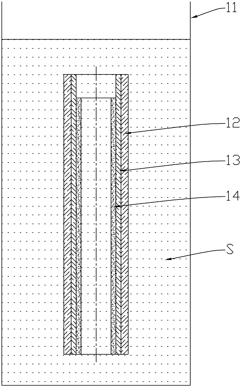
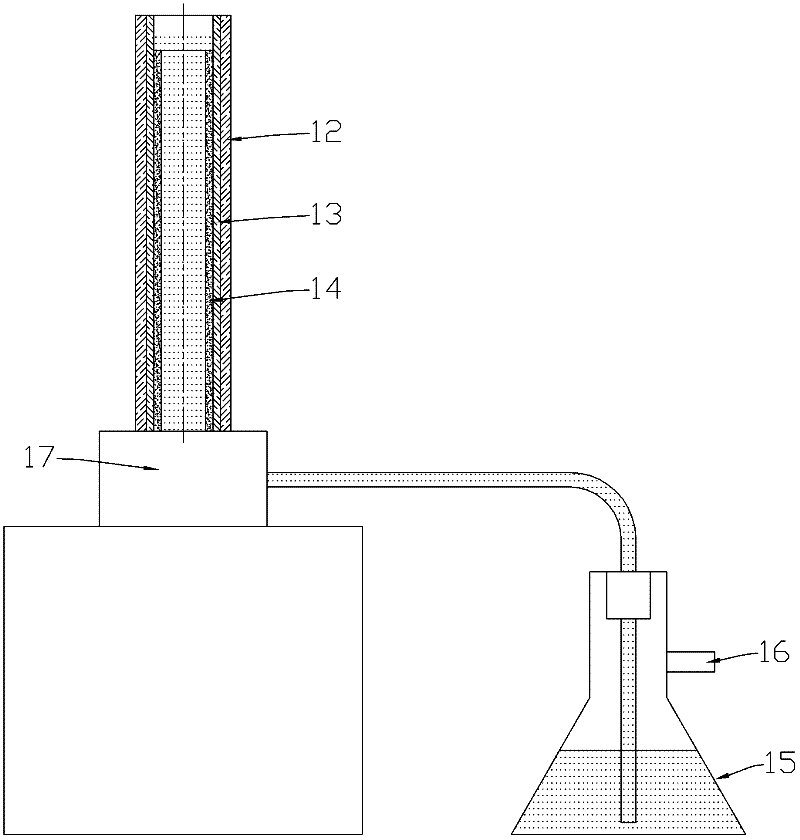
[0061] The quartz deposition tube 12 is subjected to high temperature (1800-2100° C.) flame polishing to eliminate scratches, impurities, surface unevenness and shrinkage bubbles on the surface of the deposition tube 12 . Deposit 10 layers containing SiO on the inner surface of the deposition tube 12 at 1870°C (generally within the temperature range of 1800-2000°C) 2 -P 2 o 5 -F's inner cladding 13 (the 10 layers of deposition are that the blowtorch 3 moves 10 times from the inlet end of the deposition tube 12 to the outlet end and deposits 10 times, and the actually formed 10-layer inner cladding 13 has no limit on the cross section , represented as a continuous layer, the deposition of 10 layers mentioned in the following examples is the same concept). Reverse deposition at 1550°C with SiCl 4 and POCl 3 The gas deposits a core layer 14 of loose soot. Then move the torch 3 to the inlet end of the deposition tube 12, fix the position of the torch 3 and heat the deposition...

Embodiment 2

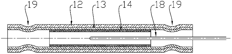
[0063] The quartz deposition tube 12 is subjected to high-temperature flame polishing to eliminate scratch impurities, surface unevenness and shrinkage bubbles on the surface of the deposition tube 12 . Deposit 10 layers containing SiO on the inner surface of the deposition tube 12 at 1870°C 2 -P 2 o 5 - Inner cladding 13 of F. Next, the torch 3 is moved to the inlet end of the deposition tube 12, and the position of the torch 3 is fixed to heat the deposition tube 12 so that its inner diameter shrinks. Reduce the deposition temperature to 1250°C and feed SiCl 4 、GeCl 4 and POCl 3 The gas deposits the loose soot core layer 14 so that the inner diameter of the loose soot core layer 14 of the deposition tube is greater than or equal to the inner diameter of the constriction 19 . Then the torch 3 is moved to the tail end of the deposition tube 12, and the temperature is raised to break the deposition tube 12, so that the tail end of the deposition tube 12 is closed. Remove...


PUM


Abstract

The invention discloses a method for manufacturing a doped optical fibre preform by MCVD (modified chemical vapour deposition), comprising the following steps of: orderly depositing an inner cladding and a loose ash core layer in a deposition tube; reducing the intake port end of the deposition tube to cause the inner diameter of the end to be less than or equal to the inner diameter of the loose ash core layer; heading and snapping the tail end of the deposition tube to close the tail end of the deposition tube; injecting solution containing rare-earth elements or transition metal elements in the deposition tube, and transversally installing the deposition tube on a lathe to soak the loose ash core layer; sintering the loose ash core layer into a glass layer; and melting-reducing the deposition tube, the inner cladding and the loose ash core layer into a solid preform. In the method disclosed by the invention, the deposition tube is horizontally placed to rotationally soak, the purpose of high-concentration doping can be realized only by the need of a small amount of rare-earth solution, and 80-90% of rare-earth solution can be saved, thereby decreasing manufacturing cost. Simultaneously, the distribution of rare-earth elements in the longitudinal direction of preform core layer is enabled to be more uniform, thereby further increasing the rare-earth doping concentration of preform core layer.

Description

technical field [0001] The invention relates to a method for manufacturing an optical fiber prefabricated rod, in particular to a method for manufacturing an optical fiber prefabricated rod whose core layer contains a dopant by using an improved chemical vapor deposition method. Background technique [0002] At present, the manufacture of optical fiber preforms generally adopts vapor deposition technology, including axial vapor deposition (vapor axial deposition, VAD), external vapor deposition (outside vapor deposition, OVD), modified chemical vapor deposition (modified chemical vapor deposition) , MCVD) and plasma chemical vapor deposition (plasma chemical vapor deposition, PCVD). Raw material SiCl for making preform 4 and dopant GeCl 4 With a high vapor pressure, it reacts with oxygen to form SiO after being evaporated by heating or bubbling 2 and GeO 2 , SiO 2 is the main component of the preform, GeO 2 The core layer incorporated into the preform raises its refrac...

Claims


Application Information

Patent Timeline
IPC IPC(8): C03B37/018
CPCC03B37/01838C03B2201/34C03B2201/40
Inventor 冯高锋葛锡良章海峰杨军勇
Owner HANGZHOU FUTONG COMM TECH CO LTD
Why Eureka
Try Eureka