Double-membrane soil pressure sensor based on hydraulic transmission

An earth pressure sensor, hydraulic transmission technology, applied in the direction of hydraulic/pneumatic measurement, instrument, measurement force, etc., can solve the problems of poor adaptability and complex calibration process, and achieve high accuracy, simple calibration and good adaptability. Effect

Inactive Publication Date: 2012-06-27
KUNMING UNIV OF SCI & TECH +1
View PDF6 Cites 15 Cited by
  • Summary
  • Abstract
  • Description
  • Claims
  • Application Information

AI Technical Summary

Problems solved by technology

Since the single-membrane plate is used, it is easily affected by soil type and earth pressure eccentricity, and has poor adaptability to various environments; during calibration, different soil properties have obvious effects on the calibration curve of the single-membrane sensor. The process is more complicated

Method used


Image

  • Double-membrane soil pressure sensor based on hydraulic transmission
  • Double-membrane soil pressure sensor based on hydraulic transmission
  • Double-membrane soil pressure sensor based on hydraulic transmission

Examples


Embodiment 1

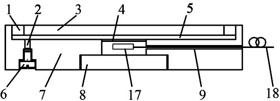
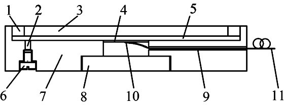
[0037] The present invention provides a structural schematic diagram of an embodiment, such as figure 2As shown: the strain gauge 10 is pasted on a diameter of the lower surface with the center point of the secondary diaphragm 4 as the center point, the strain gauge 10 is connected with the external cable 11 through the lead-out hole 9, and then the lead-out hole 9 is sealed with epoxy resin .

[0038] Sensing model for this example:

[0039] The strain distribution along the radial direction on the diaphragm is not constant. For the strain gauge pasted symmetrically at the center of the diaphragm along a certain diameter, the average value of the radial strain within the gauge length range is:

[0040] (6)

[0041] In formula (6), is the gauge length of the strain gauge.

[0042] According to the working principle of the strain gauge:

[0043] (7)

[0044] In formula (7), is the original resistance value of the strain...

Embodiment 2

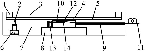
[0050] The present invention also provides an improved device, such as image 3 As shown: the secondary diaphragm 4 is in close contact with the free end of the equal-strength cantilever beam 14 through the ball 12, the ball 12 is fixed on the free end of the equal-strength cantilever beam 14, the top of the ball 12 is in contact with the free end of the secondary diaphragm 4 The lower surface is in close contact, and the contact point is the center of the secondary diaphragm 4; the fixed end of the equal-strength cantilever beam 14 is fixed inside the housing 7 with a fan-shaped fixing block 13, and the strain gauge 10 is pasted on the upper surface of the equal-strength cantilever beam 14. On the central axis, the strain gauge 10 is connected to the external cable 11 through the lead-out hole 9, and finally the lead-out hole 9 is sealed with epoxy resin.

[0051] Sensing model for this example:

[0052] Such as image 3 As shown, the deformation of the secondary diaphragm ...

Embodiment 3

[0066] Figure 4 It is a schematic diagram of the preferred structure of the present invention, wherein the secondary diaphragm 4 is in close contact with the free end of the equal-strength cantilever beam 14 through the ball 12, the ball 12 is fixed on the free end of the equal-strength cantilever beam 14, and the top of the ball 12 It is in close contact with the lower surface of the secondary diaphragm 4, and the contact point is the center of the circle of the secondary diaphragm 4; the fixed end of the equal-strength cantilever beam 14 is fixed inside the housing 7 with a fan-shaped fixing block 13, and the fiber Bragg grating 15 is pasted on On the central axis of the upper surface of the equal-strength cantilever beam 14, the fiber Bragg grating 15 is connected to the external optical cable 16 through the lead-out hole 9, and finally the lead-out hole 9 is sealed with epoxy resin.

[0067] Similar to Example 2, the wavelength shift caused by the uniform axial strain of ...


PUM


Abstract

The invention provides a double-membrane soil pressure sensor based on hydraulic transmission. The sensor employs a double layer membrane structure. A primary membrane is bonded with an outer ring of a housing by an annular membrane at an edge; and a secondary membrane is welded on an inner ring of the housing. An oil nozzle is used to enable a pressure transmission oil chamber formed between the primary membrane and the secondary membrane to be filled with hydraulic oil. A strain probe that is arranged below the secondary membrane and has a sensing element is connected with an external transmission line by a lead-out hole that is reserved and is arranged inside the housing; an epoxy resin is used for sealing the lead-out hole; and the housing and a bottom cap are threadedly connected. Therefore, a double-membrane soil pressure sensor based on hydraulic transmission is formed. According to the invention, influences caused by uneven distribution of soil pressures and difference of soil texture kinds can be eliminated; adaptability is strong; and calibration can be carried out simply.

Description

technical field [0001] The invention relates to a double-membrane earth pressure sensor based on hydraulic transmission for measuring boundary earth pressure, which belongs to the technical field of optoelectronic measurement. Background technique [0002] Earth pressure refers to the lateral pressure of the filling soil behind the retaining structure on the back of the wall due to its own weight or external load. The magnitude of the earth pressure directly determines the stability and safety of the retaining structure and the soil being retained. In reality, there are many factors that affect the earth pressure, such as the physical and mechanical properties and structural composition of the soil medium, the deformation and displacement of the retaining wall, the surface load of the filling, the condition of the groundwater, and the backfilling process of the retaining body. Numerous practices have proved that the results of observing the earth pressure in the soil are rel...

Claims


Application Information

Patent Timeline
Patent Type & Authority Applications(China)
IPC IPC(8): G01L1/02G01L1/22G01L25/00
Inventor 李川陈尔阔曹敏王达达
Owner KUNMING UNIV OF SCI & TECH
Why Eureka
Try Eureka