Diaphragm for flow battery and preparation method thereof

A liquid flow battery and diaphragm technology, which is applied to battery pack parts, fuel cell parts, circuits, etc., can solve problems such as battery performance deterioration, vanadium ion penetration, and battery efficiency reduction, and achieve excellent chemical stability and long-term The effect of working life

Active Publication Date: 2012-06-27
SHANDONG DONGYUE WEILAI HYDROGEN ENERGY MATERIAL CO LTD
View PDF4 Cites 3 Cited by
  • Summary
  • Abstract
  • Description
  • Claims
  • Application Information

AI Technical Summary

Problems solved by technology

Skyllas-Kazacos uses DuPont's Nafion membrane as the diaphragm of the all-vanadium battery to solve the problem of long-term stability of the membrane, and the phenomenon of vanadium ion penetration occurs, which leads to the self-dischar

Method used


Image

  • Diaphragm for flow battery and preparation method thereof
  • Diaphragm for flow battery and preparation method thereof

Examples


Embodiment 1

[0049] The exchange capacity is 1.35mmol / g tetrafluoroethylene and m=0, a=2, b=0, c=0, Y in the formula (III) i =SO 2 The perfluorosulfonic acid resin formed by alkali hydrolysis and acidification after monomer copolymerization of F is dispersed in DMF to form a 50% dispersion liquid, and the dispersion liquid is prepared into a film with a thickness of 30 microns by solution casting. One side spray formula (III) a=3, Y 1 , Y 2 = F and formula (V) b = 6 molar ratio 1: 1 mixture of two substances, the thickness is 5 microns, heated at 250 ° C for 60 min to obtain a flow battery separator modified by sulfonimide polycondensate .

Embodiment 2

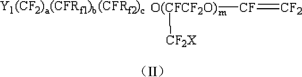
[0051] The exchange capacity is 1.00mmol / g tetrafluoroethylene and m=1, a=2, b=0, c=0, Y in the formula (II) i =SO 2 The monomer of F is copolymerized into a perfluorosulfonic acid resin formed by alkali hydrolysis and then acidification, and is dispersed in DMSO to form a 40% dispersion liquid. This dispersion liquid is prepared into a film with a thickness of 50 microns by solution casting. One side of the film is sprayed with formula (III) a=6, Y 1 , Y 2 =F and the mixture of formula (VI) d=3 molar ratio 1: 1, thickness is 2 microns, spray formula (IV) c=6 on the other side of film, X 1 、X 2 = Cl and formula (VI) d = 6 mixture of molar ratio 1:1, the thickness is 1 micron; the films sprayed on the above two surfaces are first reacted at 50°C for 100min, and then heated to 250°C for 100min to obtain One side was -SO 2 Flow battery separator modified by NHCO-polycondensate and modified by imide on the other side.

Embodiment 3

[0053] The exchange capacity is 1.20mmol / g tetrafluoroethylene and m=1, a=2, b=0, c=0, Y in the formula (II) 1 =SO 2 F monomer and m=0, a=4, b=0, c=0, Y 1 =SO 2 The monomer of F is terpolymerized to form a perfluorosulfonic acid resin through an extruder, and a film with a thickness of 80 μm is extruded at 190°C. After the above film was hydrolyzed with 10% sodium hydroxide at 80°C for 8 hours and acidified with sulfuric acid for 2 hours, the formula (III) a=6, Y was cast on one side of the film 1 , Y 2 = F and formula (VI) d = 6 mixture of molar ratio 1:1, thickness is 8 microns. Then put the film at 200°C for 3 hours heat reaction to form one side with -SO 2 NHCO-polycondensate modified flow battery separator.


PUM

PropertyMeasurementUnit
Thicknessaaaaaaaaaa
Thicknessaaaaaaaaaa
Thicknessaaaaaaaaaa

Abstract

The invention relates to a diaphragm for a flow battery and a preparation method thereof. The diaphragm is filmed by perfluorinated resin; at least one of the two surfaces of the perfluorinated resin film is provided with an imide or sulfimide condensation polymer modification layer; and the modification layer is formed from intermolecular condensation reaction between two varieties of fluorocarbon chain double functional group substances. The surface modified perfluorinated ion exchange membrane can be used as a diaphragm for a vanadium flow battery and overcome defects of high permeability of vanadium ion and huge water mobility of a Nafion ion exchange membrane; meanwhile, the diaphragm has excellent chemical stability and long service life in the battery. The invention also provides the preparation method of the diaphragm for the flow battery.

Description

technical field [0001] The invention belongs to the field of functional polymer composite materials, and relates to a liquid flow battery diaphragm with a surface modification layer and a preparation method thereof. Background technique [0002] The all-vanadium redox flow battery uses vanadium ions in different valence states as the working medium of the positive and negative electrodes to achieve the purpose of energy storage. Since the positive and negative electrodes use the same element, there will be no cross-contamination of metal ions. Compared with other batteries, this kind of flow battery has the advantages of low cost and large energy storage capacity. It is especially suitable for the storage of unstable power in the process of renewable energy generation such as solar power generation and wind power generation and the "cutting wind and filling the valley" of the power grid. It has a very broad application space in the future new energy market. [0003] The wo...

Claims


Application Information

Patent Timeline
IPC IPC(8): H01M8/02H01M2/16C08J7/06C08L27/18C08L29/10
CPCY02E60/12Y02E60/50
Inventor 唐军柯庞桂花申玉鹏安宝明杨玉清
Owner SHANDONG DONGYUE WEILAI HYDROGEN ENERGY MATERIAL CO LTD
Why Eureka
Try Eureka