Stepped impedance resonator (SIR) coaxial-cavity band-pass filter

A coaxial cavity and filter technology, applied in waveguide-type devices, electrical components, circuits, etc., can solve the problems of poor harmonic suppression characteristics, strong out-of-band suppression capability, and low in-band loss, and achieves convenient fine-tuning, The effect of low insertion loss and wide stopband

Inactive Publication Date: 2012-06-27
SHANGHAI UNIV
View PDF3 Cites 23 Cited by
  • Summary
  • Abstract
  • Description
  • Claims
  • Application Information

AI Technical Summary

Problems solved by technology

[0005] The purpose of the present invention is to provide a SIR coaxial cavity bandpass filter, the purpose is to solve the defects that the communication base station filter used in the market is too large and the harmonic suppression performance is not good, so that the filter size is much smaller than the traditional The size of the base station filter has low in-band loss, strong out-of-band suppression, and good harmonic suppression

Method used


Image

  • Stepped impedance resonator (SIR) coaxial-cavity band-pass filter
  • Stepped impedance resonator (SIR) coaxial-cavity band-pass filter
  • Stepped impedance resonator (SIR) coaxial-cavity band-pass filter

Examples


Embodiment 1

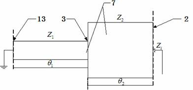
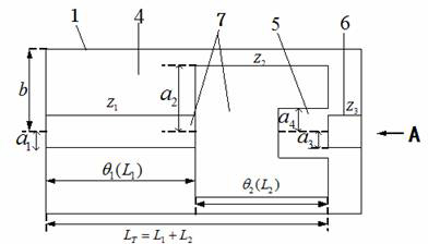
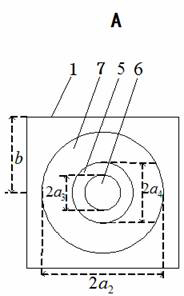
[0047] See Figure 1~Figure 9 , An SIR coaxial cavity bandpass filter, with a comb filter structure formed by coupling SIR basic resonator units. The SIR basic resonator unit consists of a rod-shaped inner metal transmission line 7, which is the same as the inner metal transmission line. The shaft’s outer cylindrical metal wall 1 and an intermediate dielectric layer 4 are composed of three parts. The intermediate dielectric layer 4 is located in the resonant cavity between the inner metal transmission line 7 and the outer cylindrical metal wall 1. The outer cylindrical metal wall 1 The upper and lower ends of the upper and lower ends are provided with outer cover plates to fix the intermediate dielectric layer 4 in the resonant cavity. The characteristic is that the inner metal transmission line 7 is composed of two coaxial transmission lines with different diameters. Step impedance converter SIR resonant rod, a large diameter coaxial transmission line forms a low impedance reso...

Embodiment 2

[0072] The technical solution of this embodiment is basically the same as that of the first embodiment, the difference lies in:

[0073] In this embodiment, the depth of the tuning screw 6 cantilevered into the open end coaxial hole 5 is adjustable, one end of the coupling screw 12 is also connected to the outer cover plate, and the other end of the coupling screw 12 cantilevered into the open The depth of the window gap 11 is also adjustable. In this embodiment, according to the needs of specific resonator design and manufacturing, the tuning screw 6 and the coupling screw 12 can be welded on the outer cover plate, or the tuning screw 6 and the coupling screw 12 can be connected to the outside through a mechanical connection mechanism. The layered cover plates are fixedly connected to facilitate tuning and strengthen the coupling effect. The step impedance converter SIR is composed of an open road surface, a short circuit surface and a step junction surface between them. The sh...

Embodiment 3

[0075] The technical solutions of this embodiment are basically the same as those of the first and second embodiments, and the difference lies in:

[0076] See Picture 10 with Picture 11 In this embodiment, the coupling structure between adjacent cavities and the SIR basic resonator unit are symmetrical. The comb filter structure formed by coupling 4 SIR basic resonator units includes two outer SIR basic resonators. Resonator units a, d and two central SIR basic resonator units b, c. In this embodiment, the coupling structure between adjacent cavities and the SIR basic resonator unit are symmetrical structures, which can be analyzed by odd-even mode theory. The SIR coaxial cavity filter of the present invention has the advantages of low insertion loss, high selectivity, and miniaturization. Type SIR is used as the basic resonant unit to form a comb filter structure, which reduces the size of the filter and controls the impedance ratio The spurious frequency can be well contro...


PUM


Abstract

The invention discloses a stepped impedance resonator (SIR) coaxial-cavity band-pass filter, which is of a comb-shaped filter structure formed by coupling an SIR fundamental resonator unit. The SIR fundamental resonator is composed of three parts of a bar-shaped inner layer metal transmission line, an outer layer cylinder metal wall in coaxial with the inner layer metal transmission line and a middle medium layer. The inner layer metal transmission line is an SIR resonance rod formed by combining two sections of coaxial transmission lines with different diameters. An open circuit coaxial bored hole and a tuning screw are arranged at the top end of the open circuit end of the metal transmission line, and the top end of the open circuit end of the metal transmission line is provided with a windowing coupling screw coupling structure and an input output direct coupling structure. The filter has good spurious frequency rejection characteristics, is small in size compared with a traditional base station, meets requirements of modern communication systems for miniaturization, low insertion loss, high selectivity and wide attenuation band on filters, and can be widely applied to modern mobile communication systems.

Description

technical field [0001] The invention relates to a band-pass filter, in particular to a 3G communication base station band-pass filter capable of realizing high performance and miniaturization, which is applied in the technical field of wireless communication. Background technique [0002] Microwave bandpass filter is an essential frequency selection device at the transmitter and receiver of modern 3G communication systems, and its performance often affects the quality of the entire communication system. With the rapid development of wireless communication, the frequency band between signals is getting narrower and narrower, which makes the requirements for filter specifications and frequency selection performance more and more stringent. [0003] Coaxial cavity filters are widely used in modern mobile communication systems because of their advantages such as high Q value, low insertion loss, high selectivity, and easy implementation. Coaxial cavity filters are also commonly...

Claims


Application Information

Patent Timeline
Patent Type & Authority Applications(China)
IPC IPC(8): H01P1/212
Inventor 李国辉胡海平徐标平胡金萍程孝奇
Owner SHANGHAI UNIV
Why Eureka
Try Eureka