Protection circuit of converter power component

An overcurrent protection circuit and power component technology, applied in the field of high-voltage power, can solve the problems of large switch volume, slow closing speed, and increased cost, and achieve the effect of simple protection circuit, reduced complexity, and compact structure

Active Publication Date: 2012-06-27
CHINA ELECTRIC POWER RES INST +1
View PDF3 Cites 19 Cited by
  • Summary
  • Abstract
  • Description
  • Claims
  • Application Information

AI Technical Summary

Problems solved by technology

Regardless of the solution, in order to ensure the reliability of the converter, there are many common problems: 1) Since the potentials of the power components of the high-voltage converter are different and they are in a higher circuit, it is difficult to use the ground potential to transmit energy. Potential energy acquisition and power supply; 2) When a series device or cascaded power component fails, the faulty part should be isolated so that it exhibits short-circuit failure characteristics and does not affect the normal operation of the rest of the equipment; 3) Fast and effective short-circuit fault current protection
The mechanical switch has the advantage of being mechanically held after bypass without requiring electrical hold, but has the following disadvantages: 1) The closing speed is relatively slow, usually at the ms level, which may lead to increased electrical stress during the bypass process and damage the device; 2) The mechanical switch needs a lot of energy when it is closed, and additional energy storage circuits are required, which increases the burden on the high-level energy-taking circuit; 3) The number of closing times is limited, and there is a large vibration when closing; 4) The volume of the switch Big
[0009] To sum up, at present, the overcurrent protection, overvoltage protection and fault bypass of power components are completed by different circuits, which makes the circuit structure complicated and the cost increased

Method used


Image

  • Protection circuit of converter power component
  • Protection circuit of converter power component
  • Protection circuit of converter power component

Examples


Embodiment Construction

[0036] The specific embodiments of the present invention will be further described in detail below in conjunction with the accompanying drawings.

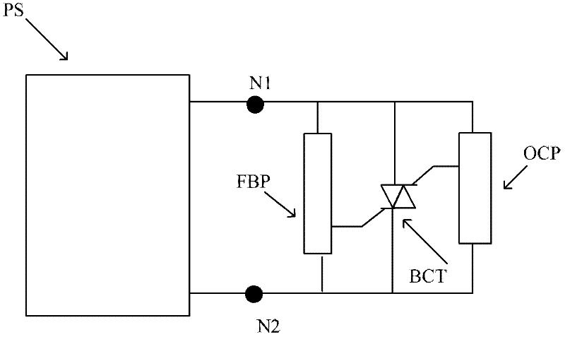
[0037] This embodiment uses only one power component for detailed description, such as image 3 Shown. In this embodiment, the two ends of the power module (PS) N 1 , N 2 Parallel fault bypass circuit FBP, thyristor BCT and overcurrent protection circuit (OCP). The fault bypass circuit means that when the power component fails, the fault bypass circuit triggers the thyristor to turn on the thyristor to bypass the power component. The overcurrent protection circuit is when the power component has an overcurrent phenomenon, the overcurrent protection circuit triggers the thyristor to turn on the thyristor to protect the power component. The thyristor is a crimp type bidirectional control thyristor, the gate I of the bidirectional control thyristor is connected to the fault bypass circuit; the gate II of the thyristor is connected to th...


PUM


Abstract

The invention discloses a protection circuit of a converter power component; and each converter comprises at least one power device. According to the protection circuit of the converter power component, both ends of each power device are parallelly connected with a fault bypass circuit, a thyristor and an over-current protection circuit respectively. When the power component fails to work, the fault bypass circuit triggers the thyristor, so that the thyristor is communicated and bypasses the power component. When the power component generates an over-current phenomenon, the over-current protection circuit triggers the thyristor, so that the thyristor is communicated and protects the power component. According to the protection circuit of the converter power component, the two-way control thyristor with good flow capacity and short-circuit failure characteristic, and the short-circuit over-current protection function of the power component and the short-circuit failure function of a fault power component are integrated. The over-current protection circuit and the fault bypass circuit based on the two-way control thyristor do not need any extra power supply, so that the burden of the high-level energy taking power supply of the power component is reduced, and the protection circuit of the converter power component is more suitable for forming cascaded multi-level high-voltage converters.

Description

Technical field: [0001] The invention relates to the field of high-voltage power, in particular to a protection circuit for a converter power assembly. Background technique: [0002] Advanced power electronics technologies represented by high-voltage direct current transmission (HVDC) technology, flexible alternating current transmission (FACTS) technology and custom power (Custom Power) technology have been used in new energy generation, power transmission and distribution, power quality management, locomotive traction, and frequency conversion. Drives and other fields have been increasingly used, making high-power power electronic technology an important foundation and means for building a strong smart grid, and it will increasingly play a more powerful role. For most of the high-voltage or UHV occasions in the power system, in order to adapt to the level of the connected AC voltage and reduce the transmission loss, it is necessary to break through the low voltage and small cap...

Claims


Application Information

Patent Timeline
Patent Type & Authority Applications(China)
IPC IPC(8): H02M1/32H02H9/02
Inventor 易荣贺之渊吕铮庞辉杨卫刚
Owner CHINA ELECTRIC POWER RES INST
Why Eureka
Try Eureka