Numerical control equipment, machining process, numerical control production line and automatic article storage system

A numerical control equipment, integrated technology, applied in metal processing, metal processing equipment, metal processing mechanical parts and other directions, can solve the problems of inaccurate positioning, movement can not be too fast, the stability of the spindle is not good, to achieve simple structure and displacement accuracy high effect

Inactive Publication Date: 2012-07-04
杨东佐
View PDF6 Cites 20 Cited by
  • Summary
  • Abstract
  • Description
  • Claims
  • Application Information

AI Technical Summary

Problems solved by technology

In the moving column type CNC machining center of this invention, since the longitudinal column on which the main shaft is installed is only supported on one side, the main shaft has poor stability, inaccurate positioning, poor movement and too fast movement during movement.

Method used


Image

  • Numerical control equipment, machining process, numerical control production line and automatic article storage system
  • Numerical control equipment, machining process, numerical control production line and automatic article storage system
  • Numerical control equipment, machining process, numerical control production line and automatic article storage system

Examples


Embodiment 1

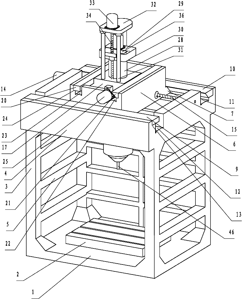
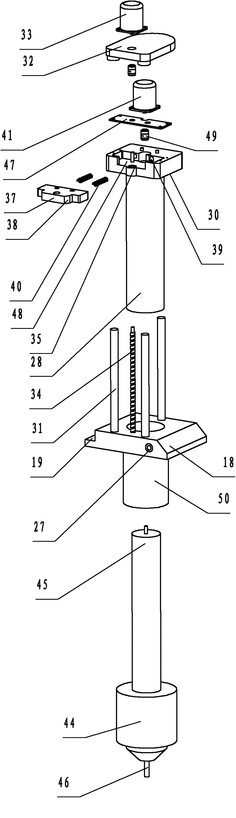
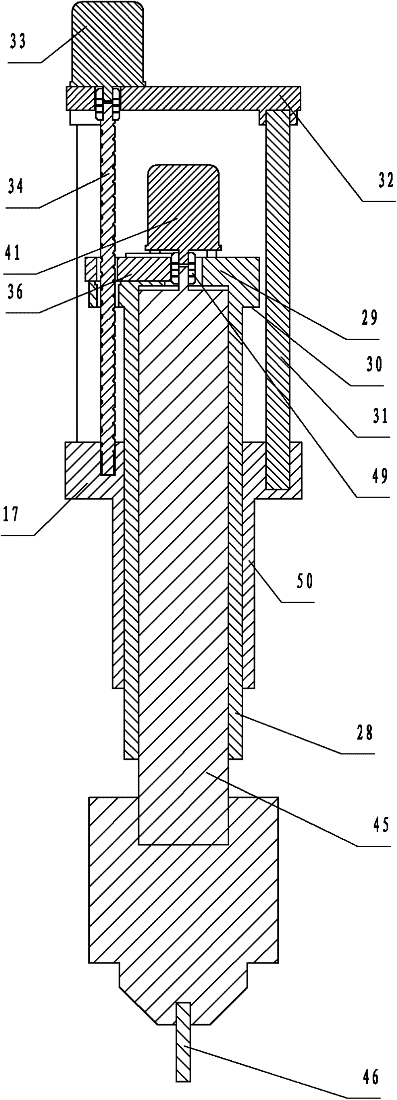
[0263] Such as figure 1 , figure 2 , image 3 As shown, a CNC machine tool includes a main frame and a workbench 2. The main body frame includes a square base 1 , a main support column 3 integrally formed with the base 1 and arranged at four corners of the base 1 , and a main support frame 4 integrally formed with the main support column 3 and arranged on the main support column 3 . The workbench 2 is fixed on the base 1. A horizontal connecting column 5 is connected to the left, right and rear directions of the main supporting column 3 . The main support frame 4 is a square closed-loop structure with an opening facing the vertical direction.

[0264] It also includes an X-direction sliding seat 6, between the main support frame 4 and the X-direction sliding seat 6, there are mutually matched X forward guide rails and X backward guide rails. The X forward guide rail and the X backward guide rail are hard rails. On the rear side of the X-direction sliding seat 6, an X-di...

Embodiment 2

[0274] Different from Example 1, as Figure 4 As shown, the Z guide rod top mount 66 is fixed on top of the Z guide rod 60 . A first swing base 61 is fixed at the bottom of the Z guide rod 60, and also includes a first swing shaft 62 mounted on the first swing base 61 in a horizontal direction and a first swing shaft motor 63 connected to the first swing shaft 62, The main machining head 65 is mounted on the first swing shaft 62 .

[0275] The Z guide bar 60 and the first swing seat 61 are fixed together. The main machining head 65 and the first swing shaft 62 are installed together.

[0276] The Z guide rod can only move up and down, and the main processing head is installed on the first pendulum axis to realize the left and right movement of the X axis, the front and back movement of the Y axis, and the swing of the pendulum axis for the up and down movement of the CNC equipment to realize four-axis linkage processing.

Embodiment 3

[0278] Such as Figure 5 As shown, the difference from Embodiment 1 is that an escape hole for installing the motor shaft and coupling 72 is provided on the Z guide rod top seat 71, and a motor 73 is fixed on the Z guide rod top seat 71, and the motor 73 The motor shaft is connected with the Z guiding rod 70 through a coupling 72 . The Z guide rod 70 can only rotate relative to the Z guide rod top seat 71 . On the Z guide rod 70, a first swing seat 74 is fixed, and also includes a horizontal first swing shaft (not shown) installed on the first swing seat 74 and a first swing shaft (not shown) through a coupling (not shown) The motor 76 to which the pendulum motor is connected. The Z guide rod 70 and the first swing seat 74 are integrally formed. The main processing head base of the main processing head 77 is integrally formed with the first swing shaft (not shown).

[0279] The Z guide rod rotates, and the structure is simple. The main processing head seat of the main proc...


PUM


Abstract

Numerical control equipment comprises a main frame, a workpiece clamping device, an X-directional sliding seat, a first driving device, Y-directional sliding seat, a second driving device and a Z-directional guide device. The main support frame is of a closed-loop structure with a vertical opening; an X-directional front guide rail and an X-directional rear guide rail which are matched with each other are arranged between the main support frame and the X-directional sliding seat; the first driving device drives the X-directional sliding seat to move back and forth and comprises an X-directional lead screw positioned between the X-directional front guide rail and the X-directional rear guide rail; the second driving device drives the Y-directional sliding seat to move back and forth; the Z-directional guide device is mounted on the Y-directional sliding seat and comprises a Z-directional guide rod capable of vertically moving, and a third driving device for driving the Z-directional guide rod to vertically move; and a main machining head is arranged at the lower end of the Z-directional guide rod. The numerical control equipment has the advantages of fine stability, accuracy in positioning and smoothness in movement, and iron scraps falling after machining a workpiece basically cannot enter the guide rail above the machining head without special protection.

Description

technical field [0001] The present invention relates to numerical control equipment and processing technology, numerical control production line, article automatic access system, especially relates to a main processing head numerical control machine tool, numerical control painting equipment, numerical control welding equipment, numerical control laser cutting equipment, numerical control laser welding equipment, numerical control plasma cutting Equipment, CNC screw loading equipment, CNC gas cutting equipment, CNC manipulator pick-up equipment, etc. Background technique [0002] Existing numerical control equipment, one is workbench movement. For example, in the invention patent with the application number of 201010284237.9, a CNC gantry vertical compound machine tool is disclosed, including a base, a workbench, and a column. The column is movably connected by a column guide rail or fixedly connected with a composite beam through a fastener. The composite beam passes throug...

Claims


Application Information

Patent Timeline
Patent Type & Authority Applications(China)
IPC IPC(8): B23Q37/00B23Q41/00B23Q1/01B23Q5/40B23Q3/00B23Q3/155B23P13/00
Inventor 杨东佐
Owner 杨东佐
Why Eureka
Try Eureka