Numerical control equipment

A kind of numerical control equipment and guide technology, applied in metal processing equipment, large fixed members, driving devices, etc., can solve the problems of fast wear of moving parts, poor stability, inaccurate positioning, etc., and achieve good guiding effect.

Inactive Publication Date: 2012-07-04
杨东佐
View PDF9 Cites 11 Cited by
  • Summary
  • Abstract
  • Description
  • Claims
  • Application Information

AI Technical Summary

Problems solved by technology

[0004] In the above-mentioned prior art, the ram on which the main shaft is installed is placed on one side of the screw rod, and is movably connected with the screw rod. The connection between the ram and the screw rod is used for bearing, and the center of gravity deviates from the axis of the screw rod. When the main shaft moves up and down, the unbalanced motion produces torsion, which makes the main shaft deviate from the direction of the screw shaft axis, resulting in poor stability and inaccurate positioning of the main shaft during movement. , Unsmooth motion, large motion inertia, and fast wear of moving parts further affect the processing accuracy

Method used


Image

  • Numerical control equipment
  • Numerical control equipment
  • Numerical control equipment

Examples


Embodiment 1

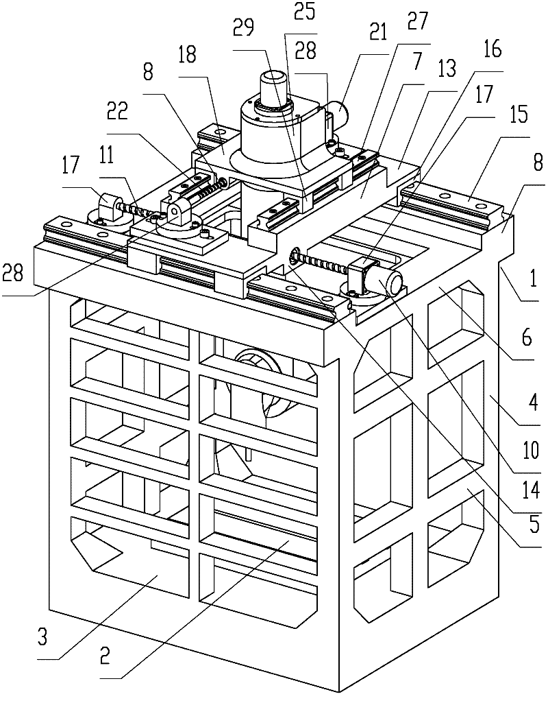
[0023] Such as Figure 1 to Figure 4 As shown, a numerical control machine tool includes a main body frame 1 and a work table 2 which are integrally formed. The main body frame 1 includes a square base 3, which is integrally formed with the base 3 and is provided with main support columns 4 at the four corners of the base 3 and at the middle positions of the left, right, and rear sides of the base, respectively, connected to the main support columns 4 Between the horizontal connecting column 5. The main support frame 6 arranged on the main support column 4 is integrally formed with the main support column 4. The main support frame 6 is a square closed-loop structure with an opening facing the vertical direction.

[0024] Also includes the X-direction sliding seat 7. Between the main support frame 6 and the X-direction sliding seat 7 are provided X forward rails and X backward rails that cooperate with each other. The X-direction sliding seat 7 can slide back and forth along t...

Embodiment 2

[0037] Such as Figure 5 As shown, a numerical control machine tool is different from Embodiment 1 in that a spindle 61 is installed in the Z guide rod 60, and the tool clamping head 62 of the main processing head is directly fixed on the spindle 60.

[0038] In the present invention, the main processing head may be provided with a tool clamping head, or the main processing head may be a paint spray head, a welding gun, a laser gun, a plasma cutting gun, a screw gun, or an air cutting gun. When the milling cutter is installed on the tool chuck, the milling function can be realized; when the grinding wheel is installed on the tool chuck, the grinding function can be realized; when the boring tool is installed on the tool chuck , Can realize the function of boring; when the drill bit is installed on the tool chuck, the function of drilling can be realized; when the main processing head is a spray head, the function of spraying can be realized; when the main processing head is a weld...


PUM


Abstract

Numerical control equipment comprises a Z-directional guide device, a sliding seat, a sliding seat fixing device, a sliding seat driving device, a workpiece clamping device, a main machining head and an electric control device. The Z-directional guide device is mounted on the sliding seat comprising a sliding seat bottom plate and a U-shaped part arranged on the sliding seat bottom plate; the Z-directional guide device comprises a Z-directional guide rod and a Z-directional guide rod driving device; two first Z-directional linear guide rails are fixedly arranged on a Y-directional sliding seat while second Z-directional linear guide rails are arranged on the Z-directional guide rod; the Z-directional guide rod can only be vertically and movably mounted together with the Y-directional sliding seat; and a main machining head is arranged below the Z-directional guide rod. By means of matching the first Z-directional linear guide rails with the second Z-directional linear guide rails to realize Z-directional guide, guide effects are fine, and the Z-directional guide rod no longer needs a rotation stop structure. When the first Z-directional linear guide rails and the second Z-directional linear guide rails are abraded, only the first Z-directional linear guide rails and the second Z-directional linear guide rails need to be replaced, while the Z-directional guide rod is not needed to be replaced.

Description

Technical field [0001] The invention relates to a numerical control equipment, in particular to a main processing head numerical control machine tool, numerical control painting equipment, numerical control welding equipment, numerical control laser cutting equipment, numerical control laser welding equipment, numerical control plasma cutting equipment, numerical control screw mounting equipment, and numerical control gas cutting equipment Wait. Background technique [0002] Existing CNC equipment with gantry structure, such as the invention patent application number 201010284237.9, discloses a CNC gantry vertical compound machine tool, including a base, a workbench, and a column. The column is movably connected by a column guide rail or through a fastener The composite beam is fixedly connected. The composite beam is movably connected by the beam guide rail or fixedly connected with more than 2 saddles by fasteners. The saddle is movably connected with the spindle device through...

Claims


Application Information

Patent Timeline
Patent Type & Authority Applications(China)
IPC IPC(8): B23Q37/00B23Q1/25B23Q5/04B23Q5/22
Inventor 杨东佐
Owner 杨东佐
Why Eureka
Try Eureka