Controllable elastic energy release and recovery system

An energy release and recovery system technology, applied in belts/chains/gears, mechanical equipment, transmissions, etc., can solve problems such as the adverse effects of mechanical braking systems, waste of recyclable energy, and lack of development, and is conducive to Environmental protection, improved utilization rate, fast effect

Active Publication Date: 2012-07-04
怀化沃普环保科技有限公司
View PDF7 Cites 12 Cited by
  • Summary
  • Abstract
  • Description
  • Claims
  • Application Information

AI Technical Summary

Problems solved by technology

However, many fields with recoverable energy have not yet developed rapidly, such as braking at high speeds or sliding from high slopes to flat ground, frequent parking of urban buses, and many elevators, tower cranes, port machinery, etc. There is a large amount of mechanical energy that can be recycled in time, wind energy and many small and medium-sized water systems, but there is no ideal mechanism that can make rational use of these energies, so that a large amount of recyclable energy (mechanical energy) is wasted in the form of friction heat. , and it is easy to have adverse effects on machinery, especially the braking system; in addition, with the development of the automobile industry, new energy vehicles continue to emerge, and the battery vehicles in new energy vehicles have limited energy storage, especially the charging time is too long Can't get faster development

Method used


Image

  • Controllable elastic energy release and recovery system
  • Controllable elastic energy release and recovery system
  • Controllable elastic energy release and recovery system

Examples


Embodiment 1

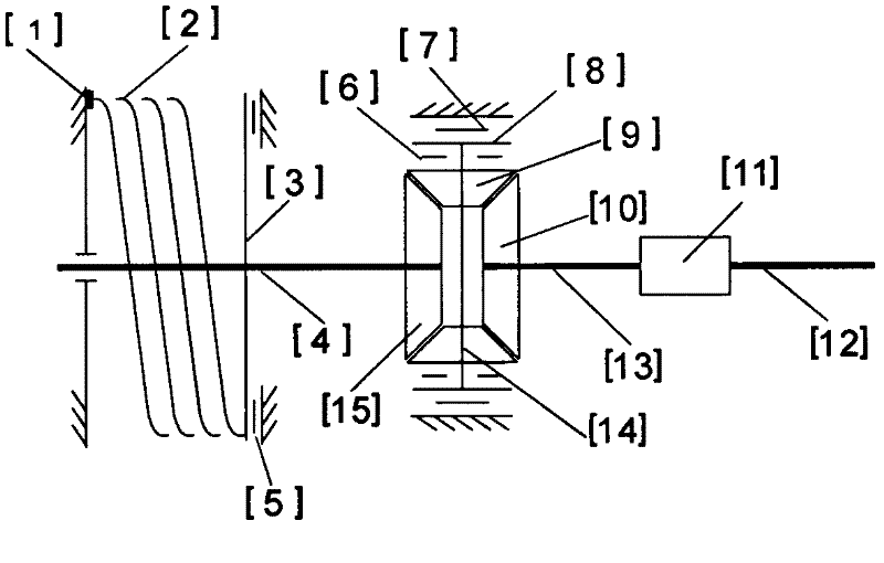
[0034] Example 1: Combining figure 1 , fix one end of the coil spring (or other elastically deformable elements or components) [2] and install the pressure sensor [1], and install the other end on the driving wheel [3] as a free end, and the driving wheel [3] is fixed on On the transmission shaft [4], a bevel gear [15] of the differential is fixed on the transmission shaft [4] as the driving bevel gear, and the other bevel gear [10] is used as the output bevel gear and is connected with the transmission shaft [13] The speed changer [11] that can bidirectionally rotate and drive is connected; Bevel gears [15] and [10], planetary wheels [9], planet carrier [14], brake disc [8] and locking mechanisms (such as clutches, brakes, Claws, etc.) [6] and [7] are used as reversing mechanisms when the system requires transmission and rotation directions to change; the pressure sensor [1] provides the control system with the pressure signal of the coil spring [2] so that the control system...

Embodiment 2

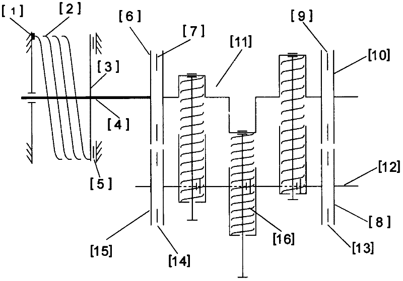
[0035] Example 2: Combining figure 2 , it is on the basis of embodiment 1, the transmission [11] uses the crankshaft stroke variable elastic continuously variable transmission [11], combined with the embodiments 1, 2, 5, 6, 7, 9 of the stroke variable elastic continuously variable transmission , 14, 15, etc., the transmission mode can choose either a compressible elastic element or component as the transmission torque of the elastic connecting rod, or a rigid connecting rod to drive the rotating coil spring transmission torque; the crankshaft stroke is variable and the elastic continuously variable transmission [11] The elastic element or assembly [16] can use a certain initial pressure or initial pressure (or energy) and an elastic element or assembly or combination that can be changed by the elastic coefficient; transmission wheel [8] and [15] and [ 10], recovery wheels [6], and locking mechanisms (such as clutches, brakes, claws, etc.) [7], [9], [13], [14] are used to chan...

Embodiment 3

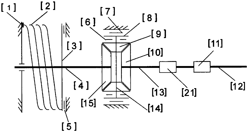
[0036] Example 3: Binding image 3, it is on the basis of embodiment 2, combined with embodiments 3, 4, 8, 10, 11, 12, 13, 16, etc. step transmission [11], since coil spring elastic elements or components cannot rotate and transmit in both directions, a suitable reversing mechanism [20] must be matched between the coil spring [2] and the coil spring elastic continuously variable transmission [11] to enable The system successfully completed the energy release and recovery tasks. The transmission mode of the coil spring variable elastic CVT [11] mainly uses the rotatable coil spring (or other elements or components that can undergo elastic deformation) to transmit torque, and the elastic component of the coil spring CVT [11] Or components can use elastic elements or components or combinations that have a certain initial pressure or elastic coefficient, or the initial pressure (or energy) or elastic coefficient can be changed, and coil spring elastic with adjustable transmission...


PUM


Abstract

The invention discloses a controllable elastic energy release and recovery system, wherein a certain amount of coil springs (or other elements or components with elastic deformation) are used as an energy storage mechanism of the system, and appropriate auxiliary devices such as transmissions (and reversing mechanisms) are equipped. Under the control of a control system, through the speed variation and torque variation of each transmission and the reversing of the reversing mechanisms, the coil springs not only can store the recoverable energy, but also can release the stored energy as required, and the energy release and recovery tasks are completed, furthermore when the output ends of the coil springs can be kept at the higher rotation speed, not only can two ends of each coil spring rotate at the same direction at different rotation speeds, the energy release or recovery speed of the coil springs can be lowered, but also two ends of each coil spring can rotate at the opposite directions, the energy release or recovery speed of the coil springs can be improved, thus the system can operate normally within the greater variable range of torque for the coil springs, the energy release and recovery tasks are completed better, and the energy utilization ratio is improved.

Description

[0001] Field of technology [0002] The present invention relates to an energy release and recovery system, specifically a coil spring (or other elements or components capable of elastic deformation) that can recover recoverable energy (mainly mechanical energy) under the control of a continuously variable transmission and a control system. After recovery, it is converted into elastic energy and stored, and the energy stored in the coil spring can be released according to needs to improve the efficiency of energy use. technical background [0003] With the continuous depletion of resources, the energy crisis has become increasingly tense, and the impact on economic development has been escalating. Countries all over the world are stepping up research and development of new energy and energy-saving technologies, including energy recovery and utilization. However, many fields with recoverable energy have not yet developed rapidly, such as braking at high speeds or sliding from h...

Claims


Application Information

Patent Timeline
Patent Type & Authority Applications(China)
IPC IPC(8): F16H33/06
Inventor 龙宏元
Owner 怀化沃普环保科技有限公司
Why Eureka
Try Eureka