Microwave vacuum drier

A microwave vacuum drying and microwave vacuum technology, which is applied in the direction of progressive dryers, dryers, and drying solid materials, can solve the problems of high labor intensity, high drying temperature of materials, and unfavorable microwave heating of dried materials, so as to improve Ergonomic and capacity-saving effect

Inactive Publication Date: 2012-07-04
周跃云 +1
View PDF10 Cites 13 Cited by
  • Summary
  • Abstract
  • Description
  • Claims
  • Application Information

AI Technical Summary

Problems solved by technology

[0003] The current microwave dryer generally has two forms: one is an in-line continuous conveying microwave dryer composed of a belt conveyor and a closed body equipped with a microwave generating device. The transmission is continuously conveyed through the microwave drying section to achieve dehydration and drying, and then the dried material is conveyed from the discharge end. It belongs to the microwave drying equipment for continuous feeding and discharging. It is 100°C, the drying temperature of the material is high, it cannot reach the low temperature drying condition, and the efficiency is low
The other is a microwave vacuum dryer with a single vacuum chamber and a microwave generating device installed on the upper part of the vacuum chamber. The middle part of the vacuum chamber is equipped with a turntable that can carry the material trays to be dried on a rotatable shaft. It is hoisted on the turret and kept relatively horizontal for rotary motion, so that the materials can be evenly dried by microwave. This kind of equipment belongs to discontinuous production equipment. One working cycle needs to complete loadin

Method used


Image

  • Microwave vacuum drier
  • Microwave vacuum drier
  • Microwave vacuum drier

Examples


Embodiment Construction

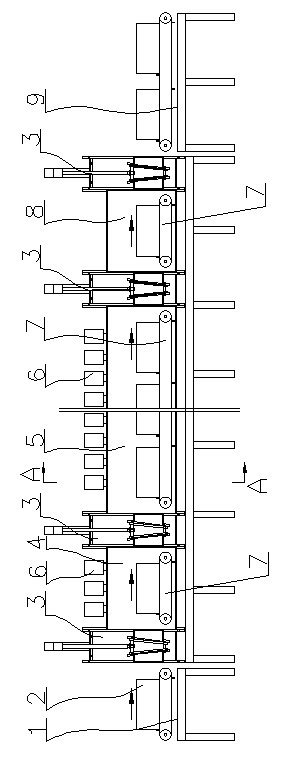
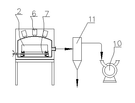
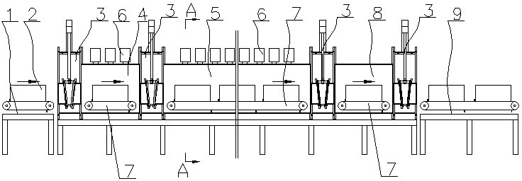
[0013] Such as figure 1 , figure 2 As shown, a microwave vacuum dryer includes a feed vacuum chamber 4, a microwave vacuum chamber 5, and a cooling discharge vacuum chamber 8 which are sequentially connected by a vacuum valve 3. The cross-section and length of each vacuum chamber are determined according to the designed drying capacity , The lower part of each vacuum chamber is provided with a stepping conveyor 7, and a vacuum valve 3 is provided at the front end of the feeding vacuum chamber 4 and the rear end of the cooling discharge vacuum chamber 8; microwave heating is provided on the upper wall of the microwave vacuum chamber 5 Device 6, (the setting of the microwave heating device 6 belongs to the prior art, and can be installed around the microwave vacuum chamber 5) is in a continuous working state during the drying process, and a microwave heating device 6 is also provided on the upper wall of the feed vacuum chamber 4 , The microwave heating device 6 on the upper wal...


PUM


Abstract

The invention discloses a microwave vacuum drier, which comprises a feeding vacuum chamber, a microwave vacuum chamber and a cooling discharging vacuum chamber, which are sequentially connected through vacuum valves. A stepping conveyor is arranged in each vacuum chamber, the vacuum valves are arranged at the front end of the feeding vacuum chamber and the rear end of the cooling discharging vacuum chamber respectively, and a microwave heating device is arranged on the side wall of the microwave vacuum chamber. The microwave vacuum drier is easier to be synchronously matched with a production line by feeding in a stepping way, microwave vacuum drying and a continuous drying way of cooling and discharging. Compared with a single-chamber microwave vacuum dryer, the microwave vacuum drier has the advantages that time for inflating the vacuum chambers after drying is complete, taking and placing feed plates and re-vacuuming after the feed plates are mounted is saved, so that working efficiency is improved; and the microwave vacuum drier is applicable to dewatering and drying for agricultural products, health care products, food, medicinal materials, fruits, vegetables, chemical raw materials and the like with high added-value and heat sensitivity, and used for low-temperature concentration of chemical products, removal of water of crystallization, dewatering and drying of traditional Chinese medicine extracts and enzyme preparations, and the like.

Description

Technical field [0001] The invention belongs to the technical field of material drying equipment, and in particular relates to a microwave vacuum dryer. Background technique [0002] Microwave heating is a kind of radiant heating. Generally, the frequency of microwave heating is 2450GHz, which makes the water molecules of the heated material oscillate, and the molecules rub against each other to generate heat, so that the inside and outside are heated at the same time, without the need for convection or conduction to transfer heat. Therefore, the heating speed is fast, the heat efficiency is high, the processing time is short, and the temperature inside and outside of the material is uniform, so energy is saved, the drying efficiency is high, and the drying quality is good. Since the boiling point of water is directly related to atmospheric pressure, the lower the atmospheric pressure, the lower the boiling point of water. For example, under one atmospheric pressure (101.3KPa), t...

Claims


Application Information

Patent Timeline
IPC IPC(8): F26B15/18F26B7/00
Inventor 周跃云蔡博
Owner 周跃云
Why Eureka
Try Eureka