Experimental device and representation method of multiphase medium high-temperature corrosion rate

An experimental device, high-temperature corrosion technology, applied in measuring devices, weather resistance/light resistance/corrosion resistance, weighing by removing certain components, etc., can solve the problem that the high temperature corrosion rate of metals cannot be accurately characterized, and the microscopic corrosion factors cannot be reflected. , can not intuitively represent problems such as high temperature corrosion

Active Publication Date: 2012-07-04
XI AN JIAOTONG UNIV
View PDF3 Cites 28 Cited by
  • Summary
  • Abstract
  • Description
  • Claims
  • Application Information

AI Technical Summary

Problems solved by technology

[0005] For the determination of high-temperature corrosion rate, the general method in the past is to weigh the sample before and after corrosion to obtain the corrosion weight gain of the sample, and use the corrosion weight gain per unit time to express the high-temperature corrosion rate. This method cannot be intuitive Indicates the progress of high-temperature corrosion; another method is to measure the thickness of the corrosion layer a

Method used


Image

  • Experimental device and representation method of multiphase medium high-temperature corrosion rate
  • Experimental device and representation method of multiphase medium high-temperature corrosion rate
  • Experimental device and representation method of multiphase medium high-temperature corrosion rate

Examples


Embodiment Construction

[0030] The structural principle and working principle of the present invention will be described in more detail below in conjunction with the accompanying drawings.

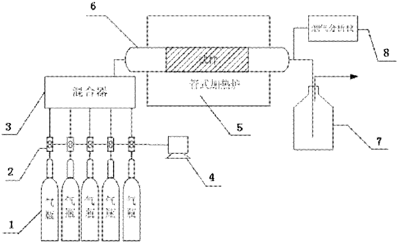
[0031] Such as figure 1 As shown, the present invention is a test device for the high-temperature corrosion rate of a multiphase medium, including a gas distribution device, a heating device connected to the gas distribution device, and an exhaust gas treatment device connected to the heating device, and the gas distribution device includes Mixer 3, at least two gas cylinders 1 communicated with the mixer 3; a mass flow meter 2 is arranged between the mixer 3 and each gas cylinder 1, and the mass flow meter 2 is connected with a computer 4, each The gas cylinder 1 is respectively filled with the gas N required for the experiment 2 , CO 2 , O 2 , H 2 S and SO 2 , each gas cylinder 1 is connected with a separate mass flow meter 2, and the mass flow meter 2 includes a gas mass controller and a gas mass flow met...


PUM


Abstract

The invention discloses an experimental device and a representation method of multiphase medium high-temperature corrosion rate. The experimental device comprises an air distribution device, a heating device and a tail gas treatment device which are communicated sequentially, wherein the air distribution device comprises a mixing device and a plurality of air bottles which are communicated with the mixing device; a quality flow meter connected with a computer is arranged among the mixing device and the air bottles; and the heating device comprises a heating furnace and a quartz tube reactor in the heating furnace. The representation method comprises the following steps: carrying out a gas phase or gas-liquid phase high-temperature corrosion experiment on a test sample according to the experiment requirement, thereby obtaining the decrement of the weights of the test sample before and after being corroded, and then converting the decrement into the thickness of the corroded test sample as the generation thickness of the corrosion layer during the test period of the test sample; and carrying out line energy spectrum line scanning experiment on the corroded test sample, thereby obtaining the maximal migration depth of a corrosive element in the thickness of the test sample, and finally calculating the high-temperature corrosion rate. By adopting the experiment device and the representation method provided by the invention, the high-temperature corrosion rate and the corrosion degree of a corrosive factor on the test sample are truly reflected from the macroscopic and microcosmic views.

Description

technical field [0001] The invention belongs to the technical field of a high-temperature corrosion rate characterization method and an experimental device, and in particular relates to a multi-phase medium high-temperature corrosion rate experimental device and a characterization method. Background technique [0002] Industrial equipment that uses coal combustion to provide thermal energy supply works in a corrosive and complex environment with high temperature and ash-containing airflow. The cross-sectional heat load and the rotational momentum flow moment of the dust-laden air flow are constantly increasing, which aggravates the tendency of furnace slagging and high-temperature corrosion. Especially in the pulverized coal burner area, due to the continuous change of combustion conditions and the adoption of low-NOx combustion technology, the A corrosive atmosphere of alternating oxidation-reduction appears in the burner area, which intensifies the high-temperature corrosi...

Claims


Application Information

Patent Timeline
IPC IPC(8): G01N5/04G01N17/00G01B15/00
Inventor 赵钦新成丁南王云刚姜薇薇周屈兰窦文宇惠世恩
Owner XI AN JIAOTONG UNIV
Why Eureka
Try Eureka