Exposure system based on control of principal component of space image

An exposure system and aerial image technology, applied in the field of exposure systems, can solve problems such as small Zernike coefficient, inability to realize closed-loop control, and difficulty in manufacturing and assembling projection objectives

Active Publication Date: 2012-07-04
SHANGHAI MICRO ELECTRONICS EQUIP (GRP) CO LTD
View PDF4 Cites 1 Cited by
  • Summary
  • Abstract
  • Description
  • Claims
  • Application Information

AI Technical Summary

Problems solved by technology

[0004] Due to the large number of Zernike coefficient items that need to be independently controlled, the number of movable degrees of freedom of the projection objective lens is large, and the conversion matrix from movable degrees of freedom to Zernike coefficients is huge. The manufacturing and assembly of the projection objective lens is extremely difficult. Extremely difficult to design and calibrate
[0005] At the same time, the usual projection objective lens is only designed and controlled for wave aberration, and there is no conversion

Method used


Image

  • Exposure system based on control of principal component of space image
  • Exposure system based on control of principal component of space image
  • Exposure system based on control of principal component of space image

Examples


Embodiment 1

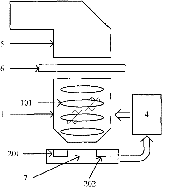
[0054] Such as figure 1 As shown, the lithography exposure system according to the present invention is composed of an illuminator 7, a silicon wafer stage 9, a projection lens 1, a reticle 8 and an exposure system control module 4, and is used to convert the pattern on the reticle 2 projected onto the silicon wafer carried by the wafer stage 9.

[0055] Such as figure 1 As shown, an aerial image sensor 201 for measuring the two-dimensional or three-dimensional light intensity distribution of the aerial image is arranged on the wafer stage 7 . A plurality of movable mirrors 101 with adjustable positions are arranged in the projection lens 1 , and the wave aberration and imaging effect of the projection lens will be changed by adjusting the positions of the movable mirrors 101 .

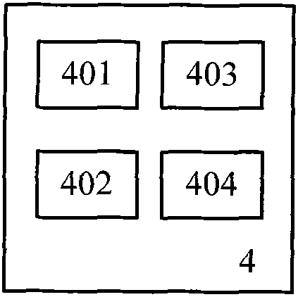
[0056] Such as figure 2 As shown, according to the lithography exposure system control module 4 of the present invention, the spatial image physical model 401 based on the Abbe imaging principle, ...

Embodiment 2

[0066] Since different lithography machines may have different configurations of related sensors, when the lithography machine itself is equipped with the wave aberration sensor 202, the following implementation manners may be adopted.

[0067] The calibration method of the control matrix is:

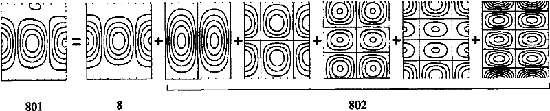
[0068] Such as Figure 6 As shown, the physical model 401 of lithography imaging is established by using the Abbe imaging principle; according to the defined illumination mode, exposure wavelength and numerical aperture, the spatial imaging 8 of the aberration-free system is calculated; multiple random input wave aberrations 803 are obtained to obtain The spatial image 801 of the aberration system; perform principal component analysis on all the calculated spatial images, and identify the principal component 802 of the spatial image of the aberration system; use the algorithm module 403 of the regression analysis method to calculate the principal component 802 of the spatial image to th...


PUM


Abstract

The invention relates to an exposure system based on the control of the principal component of a space image, sequentially comprising an illuminator, a masking plate, a projection objective lens and a silicon wafer table along the light propagation direction. A measuring unit used for measuring the space image information is arranged on the silicon wafer table. At least one movable lens of which the position can be adjusted is arranged in the projection objective lens. The exposure system based on the control of the principal component of the space image further comprises a control module. The control module is used for establishing a matrix of conversion from the position of the movable lens in the projection objective lens to the principal component of the space image according to the space image information measured by the measuring unit and calculating the position adjustment quantity of the movable lens according to the matrix of conversion so as to control the displacement of movable lens.

Description

technical field [0001] The invention relates to the field of photolithography, in particular to an exposure system in a photolithography machine. Background technique [0002] In the existing lithography equipment, in order to ensure a good exposure effect and the uniformity of the feature size to meet the process requirements, it is usually necessary to reduce the wave aberration of the projection optical system as much as possible, and at the same time reduce the wave image in the optical field of view as much as possible. Poor distribution difference, to ensure that the distribution characteristics of the spatial light intensity at the imaging end are as close to the ideal state as possible. At the same time, due to the drift of optical system performance parameters such as wave aberration caused by changes in the use environment, as well as the process characteristics of the exposure pattern, illuminator settings and other factors, during the use of the lithography machi...

Claims


Application Information

Patent Timeline
IPC IPC(8): G03F7/20
Inventor 杨志勇李亮
Owner SHANGHAI MICRO ELECTRONICS EQUIP (GRP) CO LTD
Why Eureka
Try Eureka