Environment control system of lithographic equipment

A lithography equipment and control system technology, applied in the field of lithography equipment environment control system, can solve problems such as large volume, uneven temperature, complex system structure, etc.

Active Publication Date: 2015-02-11
SHANGHAI MICRO ELECTRONICS EQUIP (GRP) CO LTD
View PDF4 Cites 0 Cited by
  • Summary
  • Abstract
  • Description
  • Claims
  • Application Information

AI Technical Summary

Problems solved by technology

[0004] This temperature control system makes the controlled object reach the expected temperature value by mixing two liquids with different temperatures. Its disadvantages are: the cold source box 220 and the heat source box 210 are used at the same time, making the system complex in structure and large in size; When the temperature difference between the cold source box 220 and the heat source box 210 is large, the temperature of the water output from the pipeline 226 is uneven because the water mixed in the pipeline 226 is not mixed by any temperature mixing device.

Method used


Image

  • Environment control system of lithographic equipment
  • Environment control system of lithographic equipment
  • Environment control system of lithographic equipment

Examples


Embodiment 1

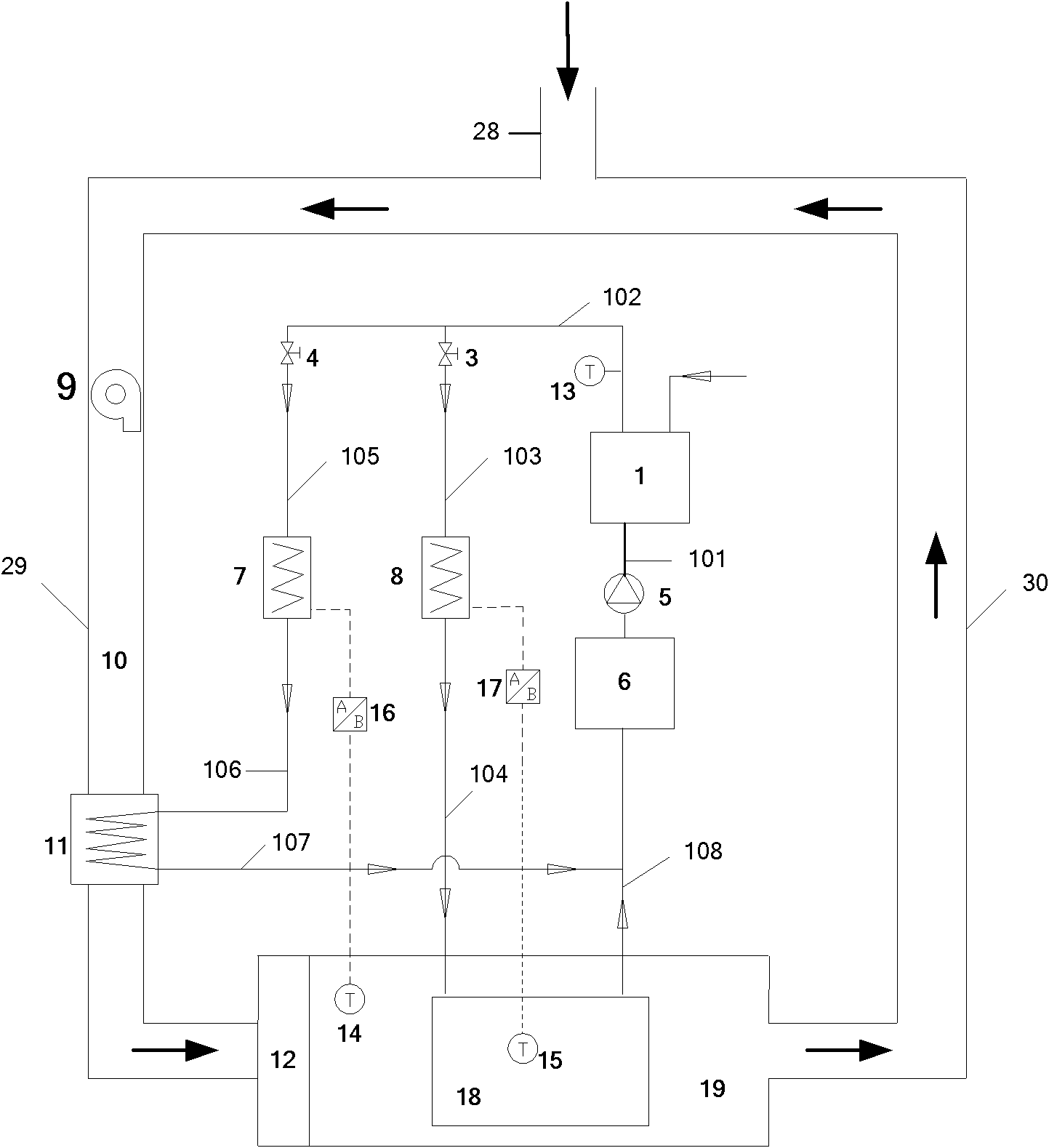
[0031] Such as figure 2 As shown, the lithography equipment environment control system of the present invention includes a controlled unit, which is a controlled object; a cooling water delivery unit that provides a cooling water source and outputs the cooling water; a temperature control unit that outputs the cooling water source from the cooling water delivery unit After temperature adjustment, to control the temperature of the controlled unit; the air delivery unit is used to deliver air to the controlled unit.

[0032] The controlled unit includes a lithography apparatus, and the lithography apparatus includes a cavity 19 and an objective lens 18 installed in the cavity 19, and the water outlet of the objective lens 18 passes through the eighth cooling water pipe 108 and the cooling water delivery unit pipe. road connection.

[0033] A static pressure chamber 12 is provided at the air inlet of the cavity 19 .

[0034] The cooling water delivery unit includes a water tan...

Embodiment 2

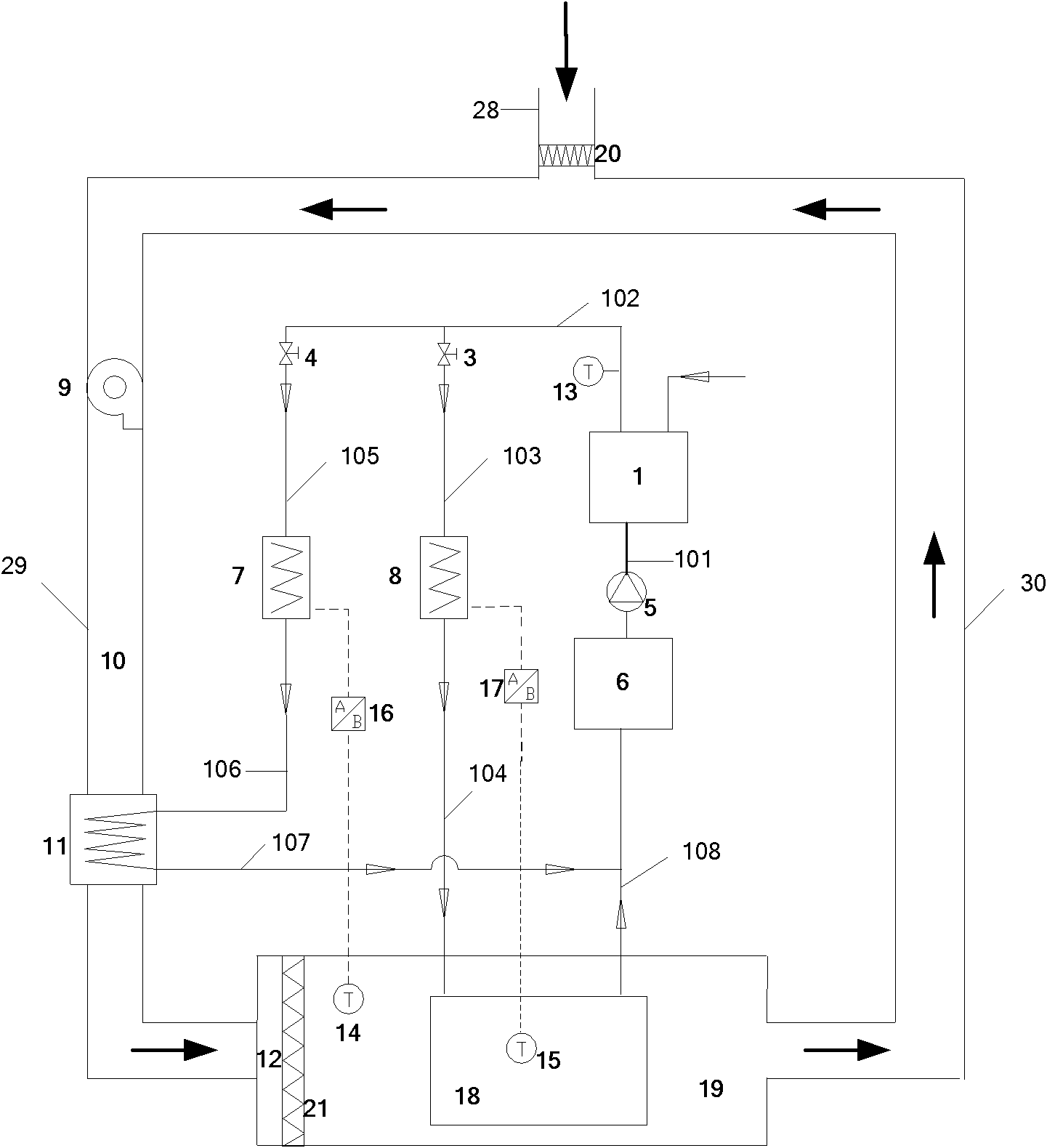
[0039] Such as image 3 As shown, this embodiment is improved on the basis of Embodiment 1, and the difference is that a primary filter 20 is installed in the air inlet 28 of the ventilation duct 10 . A high efficiency filter 21 is installed in the static pressure chamber 12 of the controlled unit.

Embodiment 3

[0041] Such as Figure 4 As shown, this embodiment is improved on the basis of Embodiment 2, and the difference is: a humidifier 22 is also installed on the air inlet duct 29 of the ventilation duct 10 of the air delivery unit, and the humidifier 22 passes through The third PID controller 24 is electrically connected with the humidity sensor 25, and the humidity sensor 25 is installed in the cavity 19 of the controlled unit. The third heater 23 is installed on the air inlet duct 29 of the ventilation duct 10 of the air delivery unit, the third heater 23 is electrically connected with the fourth temperature sensor 27 by the fourth PID controller 26, and the fourth temperature sensor 27 is installed on In the cavity 19 of the controlled unit.

[0042] The working principle of the present invention is as follows: the water pump 5 extracts water from the water tank 6, and delivers it to the refrigerator 1 through the first cooling water pipe 101, sets a temperature value for the ...


PUM


Abstract

The invention discloses an environment control system of lithographic equipment. The system comprises a controlled unit, which is a controlled object, a cooling water delivery unit, a temperature control unit and an air delivery unit, wherein the cooling water delivery unit is used for providing a cooling water source and outputting cooling water; the temperature control unit is used for adjusting temperature of the cooling water source output by the cooling water delivery unit and then controlling the temperature of the controlled unit; and the air delivery unit is used for delivering air to the controlled unit. Through the environment control system of the lithographic equipment, the temperature of the controlled unit can be accurately controlled in a refrigeration and heating mode.

Description

technical field [0001] The invention relates to an environment control system, in particular to a lithography equipment environment control system. Background technique [0002] In the field of semiconductor production, silicon wafer exposure is a process in which lithography equipment prints the integrated circuit pattern on the reticle onto the silicon wafer. During the exposure process, the lithography equipment has strict requirements on its internal temperature stability and air cleanliness. If the internal temperature of the lithography equipment drifts during operation, the overlay accuracy of the semiconductor chip will be reduced; and when the air cleanliness of the lithography equipment is low, it will directly affect the yield rate of the semiconductor chip. [0003] For this reason, a temperature control system is used to control the constant temperature of the lithography equipment. State-of-the-art temperature control systems such as figure 1 As shown, the t...

Claims


Application Information

Patent Timeline
Patent Type & Authority Patents(China)
IPC IPC(8): G03F7/20
Inventor 俞芸王飞赵滨杨志斌聂宏飞江家玮
Owner SHANGHAI MICRO ELECTRONICS EQUIP (GRP) CO LTD
Why Eureka
Try Eureka