
Method and device for continuously separating catalyst of synthetic fluid fuel in slurry bed from product

A technology of liquid fuel and separation method, which is applied in the preparation of liquid hydrocarbon mixture, separation method, liquid carbon-containing fuel, etc., can solve the problems of application limitation, high equipment investment, large area, etc., and achieves effective separation, simple structure, easy processing effect

Active Publication Date: 2012-07-11
SEDIN ENG +1
View PDF11 Cites 13 Cited by
  • Summary
  • Abstract
  • Description
  • Claims
  • Application Information

AI Technical Summary

Problems solved by technology

The membrane separation process is simple, but the separation accuracy is related to the content of solid catalyst. In the case of the same processing capacity, the higher the catalyst content, the larger the membrane separation area and the higher the equipment investment.
The magnetic separation method is highly targeted and can only be applied to iron-based catalysts, so its general use is limited
Although the combined method of cyclone-sedimentation system-membrane separation system reduces the solid content through the cyclone-sedimentation system, it can appropriately reduce the area of ​​the separation membrane and reduce equipment investment, but it has strict requirements on the limit of the catalyst content. restricted

Method used


Image

  • Method and device for continuously separating catalyst of synthetic fluid fuel in slurry bed from product
  • Method and device for continuously separating catalyst of synthetic fluid fuel in slurry bed from product
  • Method and device for continuously separating catalyst of synthetic fluid fuel in slurry bed from product

Examples


Embodiment 1

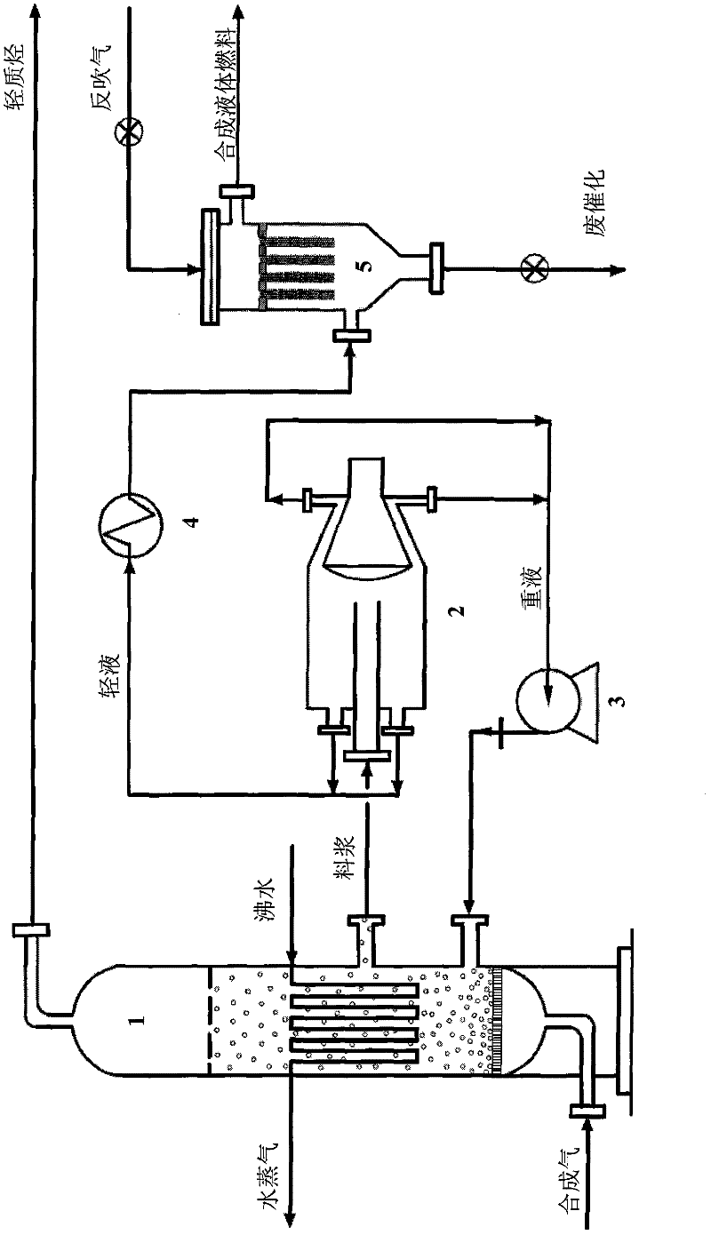
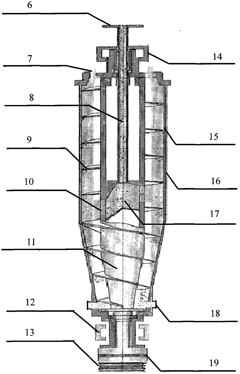
[0030] The high-speed centrifugal separator 2 is composed of a separator housing 16, a drum 15, a screw conveyor 11, a slurry inlet 6, a light liquid outlet 7 and a heavy liquid outlet 18, and is characterized in that there are two concentric centrifugal separators in the separator housing 16. The rotary parts on the main bearing 14 and the main bearing 12 of the base are respectively the non-porous drum 15 on the outside and the screw conveyor 11 inside. The main bearing 12 of the base is connected with the differential 19 and the pulley 13. The hollow shaft at the bearing 12 is connected with the casing of the planetary differential 19, and the screw conveyor 11 is connected with the main bearing 12 of the base. Between 15, the inner wall 20 is cylindrical, and the middle part of the inner wall 20 is the feeding chamber 17, and the inner wall 20 corresponding to the feeding chamber 17 has a feeding hole 10, and the inner wall 20 has a feeding center pipe 8, and the feeding ce...

Embodiment 2

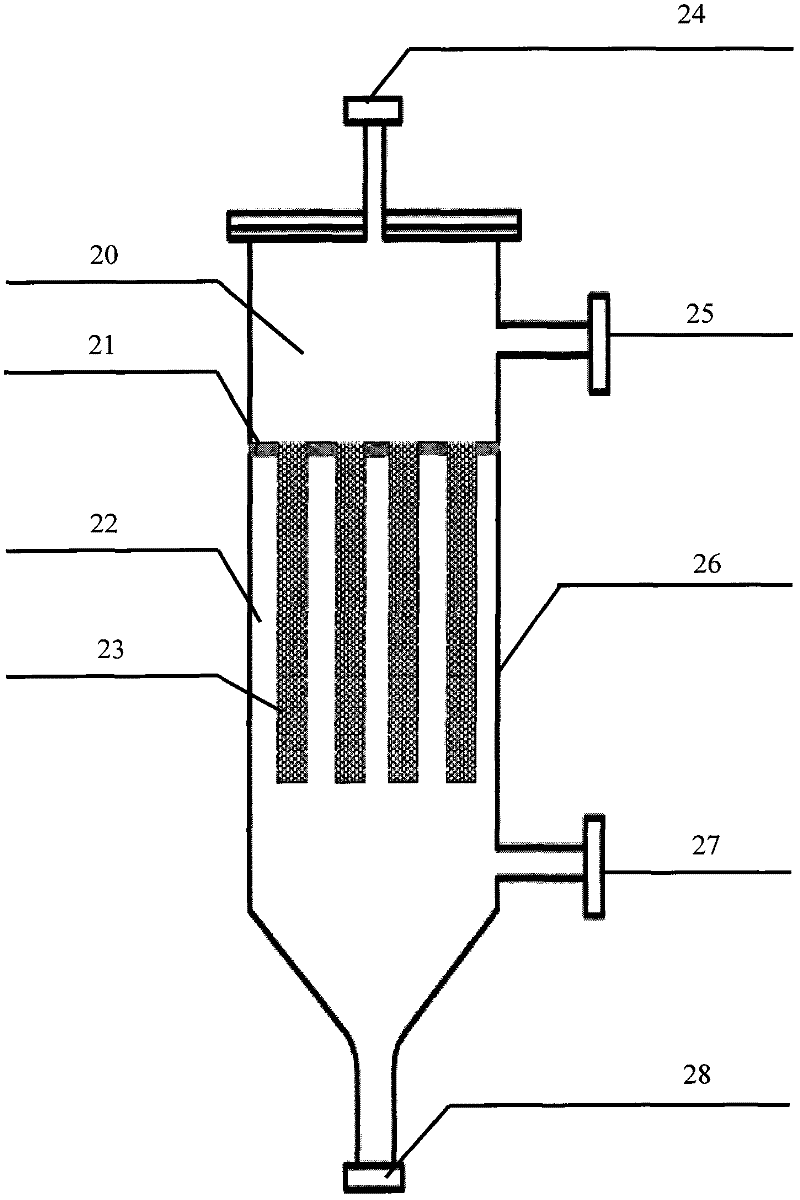
[0035] When the particle size of the catalyst used in indirect liquefaction is between 11-25 μm, the synthesis gas is passed into the slurry bed reactor 1 for catalytic synthesis reaction, and the obtained slurry is separated by a high-speed centrifuge 2 (4800-5700 rpm), After the separation, the obtained heavy oil is an oil slurry rich in catalyst quality of 78-82%, which flows out from the heavy liquid outlet 18, and is pressurized by the centrifugal pump 3 to return to the reaction zone of the slurry bed reactor to participate in the reaction, so as to realize the regular flow of the catalyst. recycle. The light liquid flows out from the light liquid outlet 7, and is heated to 285°C by the heater 4. At this time, the viscosity of the light liquid is lower than 1mPa·s. The quality of the catalyst contained in the filtrate is 20-45.60ug / g, which is sent to the fraction separation section for further processing as a product. When the sintered mesh filter 5 is subjected to seco...

Embodiment 3

[0037] When the particle size of the catalyst used in indirect liquefaction is between 26-55 μm, the synthesis gas is passed into the slurry bed reactor 1 for catalytic synthesis reaction, and the obtained slurry is separated by a high-speed centrifuge 2 (4500-5500 rpm), After separation, the obtained heavy oil is an oil slurry rich in catalyst quality of 80-87%, which flows out from the heavy liquid outlet 18, and is pressurized by the centrifugal pump 3 to return to the reaction zone of the slurry bed reactor to participate in the reaction, so as to realize the regular flow of the catalyst. recycle. The light liquid flows out from the light liquid outlet 7, and is heated to 315°C by the heater 4. At this time, the viscosity of the light liquid is lower than 1mPa·s. The quality of the catalyst contained in the filtrate is lower than 30.80ug / g, and it is sent to the fraction separation section for further processing as a product. When the sintered mesh filter 5 is subjected to...


PUM

PropertyMeasurementUnit
viscosityaaaaaaaaaa
diameteraaaaaaaaaa
particle diameteraaaaaaaaaa

Abstract

The invention relates to a method for continuously separating a catalyst of a synthetic fluid in a slurry bed from a product. The method comprises the following steps of: feeding a synthesis gas into a slurry bed reactor for carrying out catalytic synthesis reaction, leading obtained slurry to be subjected to the primary seperation of a 4000-6000 r / min high-speed centrifugal machine, and obtaining a light liquid component and a heavy liquid component, wherein the heavy liquid component is concentrated oil slurry being rich in more than 75% of catalyst, and the concentrated oil slurry is pressurized by using a centrifugal pump and returned to a reaction region of the slurry bed reactor to participate in reaction; heating the light liquid component to reach the temperature of 240-350 DEG C, leading the viscosity of light liquid to be less than 1mPa.S, leading the light liquid to enter into a multilayer metal sintering screen filter with the particle sizes of filtering meshes in the range of 0.5-20mum to be subjected to secondary seperation, and after seperation, treating filtrate containing the catalyst of less than 65.80mug.g as the product to be fed into a fraction seperation workshop section for deep processing; and carrying out back flushing on the sintering screen filter by using back flushing air when carrying out secondary seperation for 20-60 minutes by using the sintering screen filter so that the sintering screen filter is regenerated, and treating filter residues formed after back flushing as the waste catalyst to be processed. The method has the advantage that the catalyst of the synthetic fluid fuel in the slurry bed can be effectively and continuously separated from the product.

Description

technical field [0001] The invention belongs to a catalyst and product continuous separation method and equipment, in particular to a slurry bed synthetic liquid fuel catalyst and product continuous separation method and equipment. Background technique [0002] Due to the shortage of petroleum resources and the prominent contradiction between supply and demand of liquid fuel, this process is also of great significance to ensure the sustainable development of the national economy, social stability and petroleum security. There are two technical routes for coal-to-liquids: one is coal hydrogenation and direct liquefaction of synthetic oil products, which has high requirements on coal quality; the other is coal gasification into synthesis gas, and then indirect liquefaction of synthetic oil products under the action of catalysts , the method is applicable to a wide range of coal types. The two technical routes are different, the applicable coal types are different, each has it...

Claims


Application Information

Patent Timeline
Patent Type & Authority Applications(China)
IPC IPC(8): B01D36/04B01J8/22C10G2/00C07C1/04C10L1/04
Inventor 张庆庚李凡崔晓曦左永飞
Owner SEDIN ENG
Learn More