Pressure wave pulverizer for gasificatin applications
A pulverizer, pressure wave technology, applied in the direction of furnace, furnace type, hearth type furnace, etc., can solve the problems of pollutant discharge and low efficiency
Inactive Publication Date: 2012-07-11
GENERAL ELECTRIC CO
7 Cites 4 Cited by
AI-Extracted Technical Summary
Problems solved by technology
[0003] While certain methods of drying solid feedstocks are known in the art, these me...
Method used
[0063] The oxygen stream from the air separation unit is directed to a gasifier for use in producing a partially combusted gas, referred to herein as "syngas," for use as fuel by a gas turbine engine, as described in more detail herein. as stated. In some embodiments, at least some of the nitrogen process gas stream (a by-product of the air separation unit) is vented to atmosphere. Additionally, in other embodiments, some nitrogen process gas stream is injected into the combustion region within the gas turbine engine combustor to facilitate control of emissions generated within the engine, and more specifically to facilitate reduction of combustion temperature and Nitrous oxide emissions from engines. In the exemplary embodiment, the IGCC system also includes a compressor for compressing the nitrogen process gas stream prior...
Abstract
The present invention relates to a pressure wave pulverizer for gasificatin applications. The gasification apparatus includes a pressure wave pulverizer and a gasifier. The pressure wave pulverizer includes a first gas flow generator and a passage with a pulverizer inlet, a pulverizer outlet, and a gas inlet. The pulverizer inlet is supplied with the solid feedstock. The passage includes a gas acceleration section. The gas flow generator is configured to draw high speed gas through the gas inlet so as to induce pressure waves in the gas acceleration section thereby drying the solid feedstock and disintegrating the solid feedstock into particles. The gasifier is in flow communication with the pulverizer outlet.
Application Domain
Drying solid materials with heatGrain treatments +1
Technology Topic
PulverizerAirflow +2
Image
Examples
- Experimental program(1)
Example Embodiment
[0060] Examples of embodiments incorporating one or more aspects of the present invention are described and shown in the drawings. These illustrated examples are not intended to limit the invention. For example, one or more aspects of the invention may be utilized in other embodiments and even other types of devices.
[0061] The present disclosure relates to gasification applications, which include the conversion of carbonaceous materials such as coal, petroleum, biofuels or biomass into carbon monoxide and hydrogen by reacting raw materials with controlled amounts of oxygen and/or steam at high temperatures. The resulting gas mixture is a type of fuel called synthesis gas or syngas, which can include varying amounts of carbon monoxide, methane, and hydrogen. Carbonaceous substances refer to substances composed of carbon, containing carbon, or capable of producing carbon.
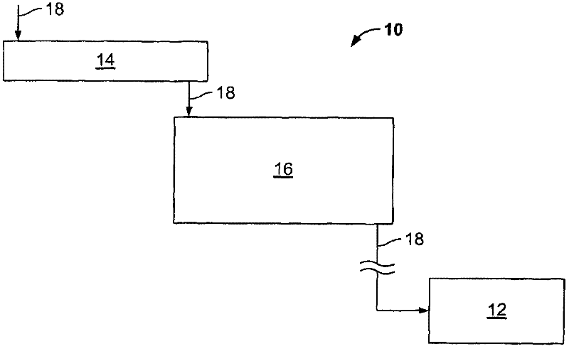
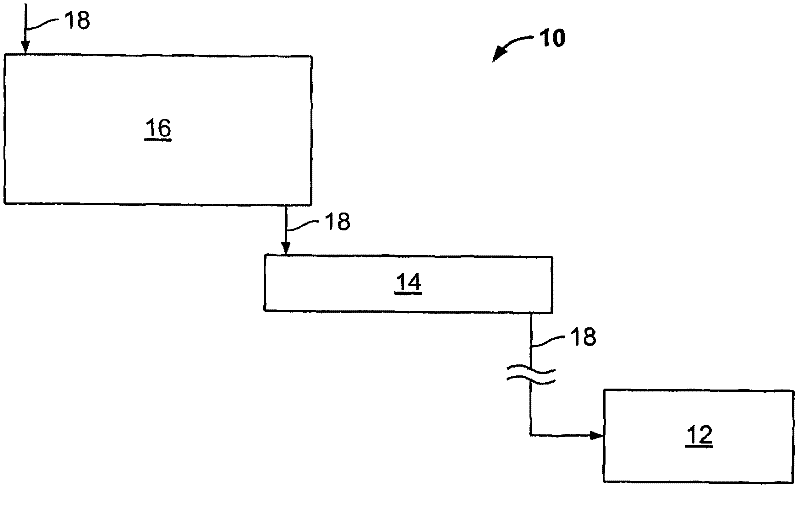
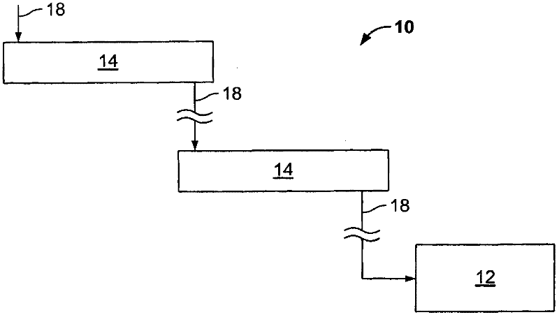
[0062] An exemplary integrated gasification combined cycle (IGCC) system may include a main air compressor, an air separation unit connected in flow communication with the compressor, a gasifier connected in flow communication with the air separation unit, and a gasifier. The gas turbine engine and the steam turbine are connected in flow communication. In operation, the compressor compresses ambient air, which is then directed to the air separation unit. In some embodiments, in addition to or as an alternative to the compressor, compressed air from the gas turbine engine compressor is supplied to the air separation unit. The air separation unit uses compressed air to generate oxygen for the gasifier. More specifically, the air separation unit separates compressed air into a separate oxygen stream and gas by-products, which are sometimes referred to as "process gas." The process gas generated by the air separation unit includes nitrogen and is referred to herein as "nitrogen process gas". The nitrogen process gas may also include other gases, such as but not limited to oxygen and/or argon. For example, in some embodiments, the nitrogen process gas includes between about 95% and about 100% nitrogen.
[0063] The oxygen stream from the air separation unit is directed to the gasifier for the production of partially combusted gas, referred to herein as "syngas", which is used as fuel by a gas turbine engine, as described in more detail herein . In some embodiments, at least some of the nitrogen process gas stream (a byproduct of the air separation unit) is vented to the atmosphere. In addition, in other embodiments, some of the nitrogen process gas stream is injected into the combustion zone in the combustor of the gas turbine engine to help control the emissions generated in the engine, and more specifically, to help reduce combustion temperature and Nitrous oxide emissions from the engine. In this exemplary embodiment, the IGCC system further includes a compressor for compressing the nitrogen process gas stream before it is injected into the combustion zone.
[0064] The gasifier converts a mixture of fuel, oxygen supplied by the air separation unit, recirculated solids, and/or liquid water and/or steam, and/or slag additives into syngas output for use by gas turbine engines Used as fuel. Although the gasifier can use any fuel, in some embodiments, the gasifier uses coal, petroleum coke, residual oil, oil emulsions, oil sands, and/or other similar fuels. In an exemplary embodiment, the syngas produced by the gasifier includes carbon dioxide. Therefore, in an exemplary embodiment, the syngas produced by the gasifier is purified in the purification device, and then is directed to the gas turbine engine combustor for its combustion. The carbon dioxide may be separated from the synthesis gas during the purification, and the carbon dioxide is discharged to the atmosphere in this exemplary embodiment. In this exemplary embodiment, the gasifier bleed connection is coupled to the waste treatment system.
[0065] The power output from the gas turbine engine is used to drive a generator, which supplies electrical power to the grid. The exhaust gas from the gas turbine engine is supplied to a waste heat steam generator, which produces steam for use by the steam turbine. The power produced by the steam turbine drives a generator, which supplies electrical power to the grid. In an exemplary embodiment, steam from a waste heat steam generator is supplied to a gasifier to generate syngas.
[0066] In an exemplary embodiment, the IGCC system includes a syngas condensate stripper that receives condensate in the syngas stream discharged from the gasifier. The condensate typically includes a certain amount of ammonia, which is dissolved in the condensate. At least a portion of the dissolved ammonia is formed in the gasifier due to the combination of nitrogen and hydrogen in the gasifier. In order to remove the dissolved ammonia from the condensate, the condensate can be boiled. The stripped ammonia is discharged from the stripping tower and directed to the waste treatment system. In an alternative embodiment, the stripped ammonia is returned to the gasifier at a pressure higher than the pressure of the gasifier, thereby decomposing in the high temperature region of the gasifier near the nozzle. Ammonia is injected into the vaporizer so that the flow of ammonia in the high temperature area close to the nozzle helps to cool the nozzle.
[0067] figure 1 with figure 2 A simplified schematic diagram of an example embodiment of a system 10 configured to dry and/or pulverize a solid feed 18 is shown. Each system is in flow communication with the gasifier 12 and may include at least one of the following two main parts: a pressure wave pulverizer 14 and a fluidized bed dryer 16. The function of the pressure wave pulverizer 14 is to pulverize and dry the solid feed 18, and the fluidized bed dryer 16 provides supplementary drying of the solid feed 18. In the overall system 10 consisting of two main parts, such as figure 1 As shown in the figure, the solid feed 18 first moves through the pressure wave pulverizer 14 and then moves downstream to the fluidized bed dryer 16. However, the order of these two main parts can be changed, and alternatively as figure 2 As shown in, the solid feed 18 may first move through the fluidized bed dryer 16 and then move downstream to the pressure wave pulverizer 14. It must be noted, however, that the fluidized bed dryer 16 need not be part of the system 10. image 3 with Figure 4 Multiple pressure wave crushers 14 are arranged in series and parallel respectively figure 1 Variant. Various devices including the fluidized bed dryer 16 can be located downstream or upstream of the pressure wave pulverizer 14, and image 3 with Figure 4 Omitted in.
[0068] The focus for the typical gasification application of the pressure wave pulverizer 14 is improved efficiency, availability, and cost compared to alternative size reduction and drying techniques. Because the pressure wave pulverizer does not require an external fuel source such as fuel gas or steam to supply energy for drying, a high overall equipment efficiency is obtained. It simply uses electricity, which can be more easily obtained in gasification equipment. Because the pressure wave crusher system is mechanically simple and easy to operate, high availability is achieved. Equipment inspection and maintenance are also simple, because the pressure wave pulverizer has a compact size and has few wear components. In addition, the device has a very short startup and shutdown time, allowing quick response to changing equipment conditions. In addition, the small base and easily available components result in low investment costs for the pressure wave crusher system. However, the disadvantage of the pressure wave pulverizer 14 itself may be limited operational adaptability and controllability in terms of solid product grinding size and moisture content. There are relatively few machine adjustment parameters during online operation to adjust product characteristics. In addition, because the residence time in the machine is low, it is not easy to correct changes in product characteristics over time. In addition, product characteristics may be affected by environmental conditions such as cold weather, high humidity, rain or snow. Therefore, a highly adjustable fluidized bed dryer can also be used to precisely control the moisture content of the product. The fluidized bed dryer is a long residence time device that has several online adjustable parameters to control the moisture content of the product. A system with both a pressure wave pulverizer and a fluidized bed dryer can be more advantageous than a separate fluidized bed dryer. In this way, the drying task is shared between the two devices. If all drying only relies on a fluidized bed dryer, the equipment will have a large base, high investment costs, and a great energy demand for heat sources such as steam. This system together with the pressure wave pulverizer and fluidized bed dryer device will provide improved efficiency, availability and cost with minimal changes in product characteristics.
[0069] A fluidized bed dryer is an example of a different type of drying system, which can be used to dry solid feed that is ground by a pressure wave pulverizer. Alternatively, the drying system may be a paddle dryer, a screw dryer, a drum dryer, a rotating disk dryer, a vibrating disk dryer, a radiation dryer, or any other large solid drying system known in the art.
[0070] Figure 5 shown figure 1 A detailed schematic diagram of the overall system 10. It must be noted that in figure 2 Will be similarly displayed in the detailed schematic Figure 5 Specific features shown in.
[0071] Image 6 An example embodiment of a pressure wave pulverizer 14 is shown, which is configured to use high velocity gas to pulverize the solid feedstock 18 and extract moisture therefrom. The pressure wave pulverizer 14 includes a channel 15 having an inlet pipe 20 with a first end 22 communicating with the ambient atmosphere (if air is used), and an opposite second end connected to the gas acceleration section 26 At the end 24, the gas acceleration section 26 can be implemented as a venturi. The inlet pipe 20 provides some distance to the gas acceleration section 26 in which the feed 18 can be accelerated to the required speed. The inlet duct 20 includes a shredder inlet 28 allowing communication with a hopper 30 that receives the feed 18 from the feed system 25 through the hopper 27. In this embodiment, the gas acceleration section 26 includes a convergent portion 32 coupled to the inlet pipe 20. The gas acceleration section 26 also includes a throat 34 which can maintain a constant diameter smaller than the diameter of the inlet pipe 20. The gas acceleration section 26 also includes a divergent portion 36 which is connected to the throat 34 and can gradually increase in diameter along the direction of the air flow 17. The gas acceleration section 26 is in communication with the airflow generator 38, and the airflow generator 38 generates an airflow, which flows from the first end 22 through the inlet pipe 20, passes through the gas acceleration section 26, and flows to the airflow generator 38. The gas flow velocity may be greater in the duct of the gas acceleration section 26 than in the inlet duct 20. The airflow generator 38 may be implemented as a fan, an impeller, a turbine, a mixture of a turbine and a fan, a pneumatic suction system, or other suitable devices for generating high-speed airflow. The airflow generator 38 is driven by a motor, and the motor can be implemented in various forms.
[0072] The airflow generator 38 includes a plurality of radially extending blades 40 that rotate to generate a high-speed airflow. The airflow generator 38 is arranged in a housing 42 which includes a housing outlet, which provides an outlet for the incoming gas. The housing 42 is coupled with the gas acceleration section 26 at the pulverizer outlet 46 and has a housing input hole (not shown) that allows communication between the gas acceleration section 26 and the inside of the housing 42. The blade 40 defines a radially extending flow passage 44 through which the gas is conveyed to the outer shell outlet 48 on its periphery to allow the pulverized feed 18 to exit.
[0073] In operation, the feed 18 is introduced into the inlet pipe 20 by a number of conveying methods. Although it is envisaged that the feed material 18 will be solid, the pressure wave pulverizer 14 can also be used to dry and pulverize semi-solid materials. The airflow generator 38 generates airflow ranging from 350 mph to supersonic speed, which flows through the inlet duct 20 and the gas acceleration section 26. In the gas acceleration section 26, the gas flow velocity is greatly accelerated, and the feed material 18 is pushed toward the gas acceleration section 26 by the high-speed gas flow. The feed 18 is smaller in diameter than the inner diameter of the inlet pipe 20, and there is a gap between the inner surface of the inlet pipe 20 and the feed 18.
[0074] In this embodiment, when the feed material 18 enters the convergent portion 32, the gap becomes narrower, and eventually the feed material causes a great reduction in the area of the convergent portion 32 through which gas can flow. The recompression shock wave traces from the rear of the feed material and forms an arcuate shock wave in front of the feed material. There is a standing shock wave where the convergent part 32 meets the throat 34. The effects of these shock waves impact the feed 18 and cause the crushing and dehumidification of the feed 18. The crushed feed material 18 continues to pass through the gas acceleration section 26 and exits into the gas flow generator 38.
[0075] The gas acceleration section 26 provides a point of impact between the higher velocity shock wave and the lower velocity shock wave. The pressure wave provides pulverization and dehumidification in the gas acceleration section 26. In operation, there are no visible signs of moisture in the interior of the gas acceleration section 26 or in the housing outlet 48. The amount of moisture removed is quite large, although residual amounts may remain.
[0076] The size reduction of the feed material depends on the feed material to be crushed, the size of the pressure wave crusher 14, and the machine operation settings. For example, for some materials, by increasing the speed of the airflow, pulverization and particle size reduction are increased. Thus, the pressure wave pulverizer 14 allows the user to change the desired particle size by changing the air flow velocity.
[0077] The feed material, moisture and air flow pass through the air flow generator 38 and exit through the housing outlet. The housing outlet 48 is coupled to the exhaust pipe 50, which conveys the feed material to a particle collector 52, such as a cyclone for separating the feed material 18 and the gas 53. The diameter of the exhaust pipe 50 affects the amount of further drying that occurs. A large amount of gas is required for further drying of the feed material. In the exhaust pipe 50, the gas moving faster in the exhaust pipe 50 conveys the feed material 18 and removes moisture remaining on the feed material. The gas and vapor move to the particle collector 52 where they are separated from the solid feed.
[0078] The pulverization can generate heat, which helps to dry the feed material. In addition to crushing, the rotation of the airflow generator 38 can generate heat. The size between the housing 42 and the airflow generator 38 may be such that friction generates heat during rotation. The heat can leave the housing outlet 48 and exhaust pipe 50 and further dehydrate the feed as it moves to the particle collector 52.
[0079] The diameter of the casing outlet 48 can be increased or decreased to adjust the resistance and heat passing through the casing outlet 48 and the exhaust pipe 50. The diameters of the exhaust pipe 50 and the housing outlet 48 affect the removal of moisture from the crushed feed material. The pulverization and dehumidification increase as the airflow generated by the airflow generator 38 increases. If the air flow is increased or decreased, the diameter of the exhaust pipe 50 and the housing outlet 48 can be reduced to provide the same dehydration of the feed material.
[0080] Heavier materials with less moisture, such as rocks, require less dehumidification. For such materials, the diameter of the housing outlet 48 and exhaust pipe 50 can be increased as less drying is required. Therefore, for relatively wet materials, the diameter of the shell outlet 48 and the exhaust pipe 50 can be reduced to increase the quantity and heat of the gas, so as to achieve proper dehydration of the feed material 18.
[0081] The inclination angle of the exhaust pipe 50 with respect to the longitudinal axis of the gas acceleration section 26 and the airflow generator 38 may also affect the dehydration performance. The upwardly moving material returns by gravity, while the gas is less restricted by gravity. This allows the gas to move faster than the feed material and can increase moisture removal.
[0082] A particle collector 52, such as a cyclone, is a device for separating particles from a gas stream. The cyclone 52 typically includes a settling chamber in the form of a vertical cylinder. The swirler 52 can be implemented with a tangential inlet, an axial inlet, a peripheral discharge outlet, or an axial discharge outlet. The airflow and particles enter the cylinder through the inlet, and rotate in a vortex as the airflow travels down the cylinder. The cone section causes the diameter of the vortex to decrease until the gas itself reverses and rotates upward from the center to the outlet. The particles are centrifuged to the inner wall and collected by inertial impact.
[0083] Other aspects of the pressure wave pulverizer 14 are described in US Patent Application Publication No. 2009/0214346 to Graham et al. Other embodiments of the pressure wave pulverizer 14 that do not include the exact features described herein or in the Graham citation can be used. Other machines that rely on the same principles can use other methods to generate pressure waves or high-speed vortices, which contain large amounts of kinetic energy. For example, the machine may not include a venturi section, and may include other features, such as a vortex stabilizer.
[0084] Figure 7 An alternative embodiment of the pressure wave pulverizer is shown, which does not include a venturi section upstream of the airflow generator 38 and includes a vortex stabilizer 33. The vortex stabilizer 33 provides an attachment point for the gas vortex 35 generated by the gas flow generator 38 rotating at a high speed.
[0085] See back Figure 5 , Which schematically shows an exemplary embodiment of the fluidized bed dryer 16. The bed dryer 16 includes a bed dryer housing 54 which defines a chamber 64 through which the feed material 18 to be dried passes. The bed dryer housing 54 includes a bed inlet 56, a bed outlet 58, a process gas inlet 60 and a process gas outlet 62. The feed 18 is supplied through a bed inlet 56 that can be positioned on one end of the fluidized bed dryer 16 and exits through a bed outlet 58 that can be positioned on the opposite end of the fluidized bed dryer 16. in Figure 5 In the embodiment, the feed 18 has been pulverized, and may have been appropriately dried at the pressure wave pulverizer 14, and after passing through the particle collector 52, it reaches the fluidized bed dryer 16, where the particles and gas are fed Separate. Because the feed 18 is in the state of being pulverized particles, the feed particles can be moved through the chamber 64 by mixing the particles with the process gas 66, and the process gas is guided from the bed inlet 56 to the bed by a gas flow generator 67 such as a blower. Exit 58. The process gas 66 is in a heated state, and may be steam, nitrogen, carbon dioxide gas, one type of inert gas, or the like. If the solid of the feed 18 is larger than the particle state, it may be difficult to make the feed 18 move in the chamber 64 by using the process gas 66. In this case, the movement of the larger solid of the feed material 18 may alternatively be produced by various mechanisms, such as vibrating movement, conveyor belt, extrusion screw, and so on.
[0086] The feed 18 travels along a predetermined path 68 through which the feed passes through the chamber 64, and the process gas 66 passes through the chamber 64 along the process gas path 70. The process gas path 70 is provided to pass through a predetermined path 68 so that the process gas path 70 and the predetermined path 68 are arranged in a cross-flow relationship, where the paths 68 and 70 intersect each other. Such an arrangement allows heat exchange to occur between the process gas 66 and the feed 18 so that moisture can be extracted from the feed 18. although Figure 5 The embodiment in shows a substantially orthogonal arrangement of the process gas path 70 and the predetermined path 68, but this is not necessary, and the process gas path 70 may form an acute angle with the direction of the predetermined path 68. In an exemplary embodiment, the process gas inlet 60 is provided at the lower part of the bed dryer housing 54 and the process gas outlet 62 is provided at the upper part of the bed dryer housing 54 so that the hot process gas 66 can be naturally The ground rises and leaves the bed dryer housing 54.
[0087] After the process gas 66 has provided heating for the feed 18 and has exited the bed dryer housing 54 through the process gas outlet 62, the process gas 66 can be reprocessed so that it can provide heating for the feed 18 and then recycled To the process gas inlet 60. Although the present embodiment provides a recirculation system for the process gas 66, a fluidized bed dryer 16 in which the process gas 66 simply flows through without recirculation is conceivable.
[0088] During recirculation, the process gas 66 may be directed to a particle collector, which may remove any particles of the feed 18 from the process gas 66, which has left the bed dryer housing 54 instead of being directed to the bed outlet 58. In one embodiment, the particle collector 72 may be a cyclone, and may guide the particles of the feed 18 separated from the process gas 66 to the bed outlet 58. In addition, a condensing coil 74 may be provided in the recirculation system to remove moisture 75 from the process gas 66 whose moisture content increases in the chamber 64. In addition, the recirculation system may include a heating coil 76 provided to reheat the process gas 66 that has been cooled due to heat exchange with the feed material 18 inside the chamber 64. In addition, because some of the process gas 66 may be lost when passing through the recirculation loop, it may be necessary to make up for such loss of process gas 66 during recirculation.
[0089] In order to supplement the drying of the feed material, a set of heating coils 78 may be provided in the chamber 64 along a predetermined path 68 between the bed inlet 56 and the bed outlet 58 to allow the feed 18 to pass through the chamber 64 Feed 18 extracts moisture. The heating coil 76 may undergo direct heat exchange with the feed 18. Thus, moisture can be extracted from the feed by heating the coil 78 or the process gas 66.
[0090] The pressure wave pulverizer 14 or the combination of the pressure wave pulverizer 14 and the fluidized bed dryer 16 is in flow communication with the gasifier 12. Figure 8 with Picture 9 It is helpful to explain the term "in flow communication with..." by illustrating an example of the process that the solid 18 undergoes during movement between two or more pressure wave pulverizers 14, fluidized bed dryer 16 and gasifier 12 ".
[0091] Figure 8 A specific embodiment of a specific feeding system 100 is shown, which includes a fan 102, a bladder-type dust chamber 104, a cyclone 106, a screen 108, a first weighing belt feeder 110, a raw coal charging hopper 112, a first Two weighing belt feeder 114, hammer mill 116, pressure wave pulverizer system 118, pneumatic transport pick-up box 120, crushed coal storage 122, high-pressure Bosmetric feeder 124, transport container 126 and gasifier 128. The raw coal from the charging hopper 112 is conveyed to the pressure wave pulverizer system 118 using the second weighing belt feeder 114. The solids are crushed, dried, separated from the air flow in the pressure wave crusher system 118, and screened. Oversized particles are returned to the inlet of the pulverizer system 118 downstream of the screen 108 by using the first weighing belt feeder 110. Downstream of the pressure wave pulverizer system 118, the solids are stored in a hopper (e.g., pneumatic handling pick-up box 120), and transported vertically pneumatically to another storage hopper (e.g., crushed coal storage 122). Then a feeding device, such as a positive displacement solid pump or a high-pressure Posmetric feeder 124, feeds the solids into the high-pressure vessel (for example, the handling vessel 126). The solids are then transported from the high-pressure vessel to the high-pressure gasification chamber of the gasifier 128.
[0092] Figure 9-11 The alternative system is described in a more general way. These diagrams show the pressure wave pulverizer 14 and the combination of the pressure wave pulverizer 14 and the fluidized bed dryer 16, which are in flow communication with the gasifier 12. The raw material solid 18 is turned into fine particles at the pulverizer 14 (step 130). The feed solids 18 can also be further dried at the fluidized bed dryer 16 (step 132), although the order of steps 130 and 132 are interchangeable, such as Picture 10 with Picture 11 Shown. As a result, the solid 18 is brought to a ground and dry state (step 134). Then, the solid 18 is delivered to the high-pressure environment through the solid feeding device (step 136), and then stored in the solid handling container or system (step 138). The solid feeding device can consist of many mechanisms, such as lock hoppers, rotary valves or other types of solid feeding devices. There are many options for solid handling systems, including mechanical systems and pneumatic systems. The gasifier 12 can operate within a pressure range and can have many geometric features. For example, the gasifier 12 may have a single or multiple injection locations, and injection may occur at the top, bottom, or sides, or a combination thereof.
[0093] The present invention has been described above with reference to the exemplary embodiments. Others will think of variants and modifications after reading and understanding this manual. Example embodiments incorporating one or more aspects of the present invention are intended to include all such variations and modifications as long as they are within the scope of the appended claims.
PUM


Description & Claims & Application Information
We can also present the details of the Description, Claims and Application information to help users get a comprehensive understanding of the technical details of the patent, such as background art, summary of invention, brief description of drawings, description of embodiments, and other original content. On the other hand, users can also determine the specific scope of protection of the technology through the list of claims; as well as understand the changes in the life cycle of the technology with the presentation of the patent timeline. Login to view more.