Eureka AIR delivers breakthrough ideas for toughest innovation challenges, trusted by R&D personnel around the world.

Multi-station and multi-parameter vision measuring system and method for rotary parts

A visual measurement and parameter measurement technology, applied in the field of measurement and testing, can solve the problems of difficult multi-parameter detection of complex parts, reduce the detection speed of visual inspection equipment, low data processing ability and speed, etc., and achieve fast measurement speed and automation High, guaranteed quality effect

Inactive Publication Date: 2012-07-11
ZHEJIANG UNIV
View PDF6 Cites 43 Cited by
  • Summary
  • Abstract
  • Description
  • Claims
  • Application Information

AI Technical Summary

Problems solved by technology

The automatic focusing system and the self-adaptive adjustment light intensity illumination system disclosed in the high-precision visual inspection system (200710177204.2) not only need to adjust the position of the optical imaging system in real time through a high-precision feeding mechanism during the inspection process, but also need to adjust the position of the optical imaging system according to the The quality of the collected images is used to adjust the output light intensity of the lighting source, thereby reducing the detection speed of the visual inspection equipment; The data processing capability and speed are lower than those of PC-based visual inspection systems, making it difficult to realize multi-parameter inspection of complex parts

Method used


Image

  • Multi-station and multi-parameter vision measuring system and method for rotary parts
  • Multi-station and multi-parameter vision measuring system and method for rotary parts
  • Multi-station and multi-parameter vision measuring system and method for rotary parts

Examples


Embodiment Construction

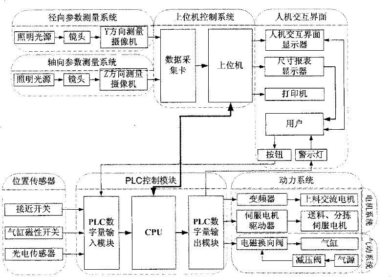
[0034] A schematic diagram of the product structure of a multi-station multi-parameter visual measurement system and method for rotary parts of the present invention is as follows figure 1 As shown, it includes Y-shaped feeding mechanism, multi-station chain feeding mechanism, radial parameter measuring device, axial parameter measuring device, warehouse-type three-dimensional sorting mechanism, PLC control module, man-machine interface, and host computer control system and fuselage.

[0035] The Y-shaped feeding mechanism for conveying the rotary parts (13) to the feeding waiting area (10) one by one and for sorting the rotary parts (13) according to qualified products, reworked products and scrapped products The categorized warehouse-type three-dimensional sorting mechanisms are all located on one side of the multi-station chain-type feeding mechanism for precise conveying and positioning of the rotary parts (13) in the feeding waiting area (10) for axial and radial measurem...


PUM


Abstract

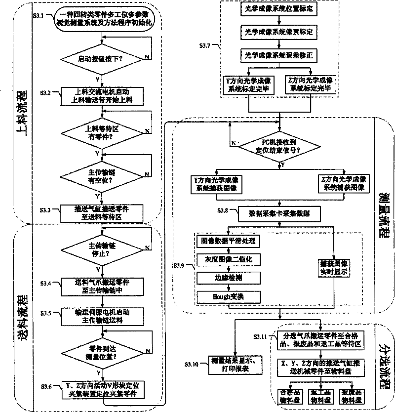
The invention discloses a multi-station and multi-parameter vision measuring system and method for rotary parts. The multi-station and multi-parameter vision measuring system comprises a Y-shaped feeding mechanism, a multi-station chain type feeding mechanism, a radial parameter measuring device, an axial parameter measuring device, a warehousing type three-dimensional sorting mechanism, a PLC (Programmable Logic Controller) control module, a human-machine interaction interface and an upper computer control system. The invention can provide geometrical quantity precision measuring equipment for the quality control of processing of the rotary parts on industrial field. The geometrical quantity precision measuring equipment can be used for detecting the geometric dimension error, shape error and position error and counting and analyzing the detection result of the same batch of parts to grasp the fluctuation condition of the batch quality of products. Meanwhile, the equipment has functions of automatically feeding parts and automatically sorting according to the measuring result and can be directly connected in series to the production line in series for on-line and full-detection of the parts.

Description

technical field [0001] The invention relates to the field of measurement and testing, in particular to a visual measurement and automatic sorting system for geometric dimensions, shapes and position errors of rotary parts. Background technique [0002] The measurement of the geometric size, shape and position error of mechanical parts is an important link to ensure the accuracy and quality of products. Due to the diversity and complexity of mechanical parts, the measurement methods for the geometric quantities of different parts are also different. Usually, the geometric quantity measurement method mainly uses workers to measure parts by using mechanical, electronic, pneumatic and optical measurement tools, but most of them have shortcomings such as being affected by human factors, low degree of automation, and low measurement efficiency. , it is difficult to meet the quality control requirements of large batches of parts. [0003] With the standardization and legalization...

Claims


Application Information

Patent Timeline
IPC IPC(8): B07C5/04B07C5/02G01B11/02G01B11/08G01B11/24G01B11/26G01B11/00
Inventor 余忠华洪涛夏嘉廷
Owner ZHEJIANG UNIV
Why Eureka
Eureka Blog
Learn More