Method and device for operating a resistance welding device

A technology of resistance welding and triggering device, applied in welding power supply, welding power supply and other directions, can solve the problem of increased switching loss, etc., and achieve the effect of small resistance, small volume, and less magnetization loss

Active Publication Date: 2016-05-11
ROBERT BOSCH GMBH
View PDF5 Cites 0 Cited by
  • Summary
  • Abstract
  • Description
  • Claims
  • Application Information

AI Technical Summary

Problems solved by technology

However, if the switching frequency is increased, the switching losses also increase when the semiconductor components required for this are activated by means of known pulse width regulation methods

Method used


Image

  • Method and device for operating a resistance welding device
  • Method and device for operating a resistance welding device
  • Method and device for operating a resistance welding device

Examples


Embodiment Construction

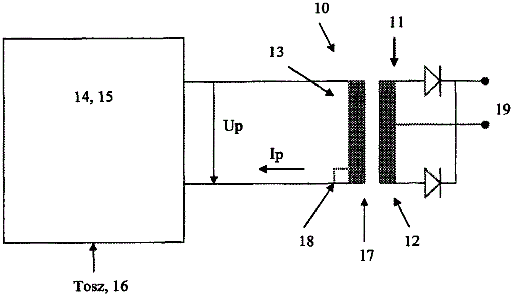
[0025] attached figure 1 A medium frequency welding transformer with a rectifier and a converter is shown schematically and is generally designated with reference numeral 10 . Device 10 can be divided into different components. The device has a primary circuit 13 and secondary circuits 11 , 12 , which are connected via a transformer 17 in such a way that a common magnetic flux is generated within the windings of the primary circuit 13 and the secondary circuits 11 , 12 . The primary winding 13 with the number of turns of the transformer 17 being N1 is connected to the primary circuit and the number of turns of the transformer 17 is respectively N 2 +N 3 The secondary windings 11, 12 are connected to the secondary circuit. The transformer 17 also has a transformer core, but this is not shown here for the sake of clarity.

[0026] In the secondary circuit 11 , 12 there is an output area indicated by reference numeral 19 , to which a welding electrode can be connected. In th...


PUM


Abstract

The polarity of the direct voltage and the number of drive pulses during a time period of the drive device (14) are varied, without changing the pulse width of the drive pulses from outside of the normal circuit tolerances. The pulse width of the drive pulses during the welding operation is within the normal tolerances of the drive device and kept constant. The magnetic flux density of welding transformer (17) is detected by a flux density sensor (18). An independent claim is included for resistor welding device.

Description

technical field [0001] The invention relates to a method and a device for operating a resistance welding device, in particular by means of a (single-phase) medium-frequency welding transformer having a transformer core, a primary winding and a secondary winding. [0002] Although the following basically refers to medium frequency welding transformers, the invention is not limited thereto. Background technique [0003] Intermediate frequency welding transformers, to which a square wave alternating voltage is usually supplied by a current commutator, have been used in welding processes for some time. The transformer outputs a high-current low voltage at its secondary winding, which is subsequently rectified and used for the welding process. The frequency of operation of the intermediate frequency transformer is high, such a high frequency enables efficient energy conversion and thus the use of a relatively small and light transformer. Of course, hysteresis effects or saturat...

Claims


Application Information

Patent Timeline
Patent Type & Authority Patents(China)
IPC IPC(8): B23K11/24
CPCB23K11/241
Inventor R·肖尔茨W·迈斯特
Owner ROBERT BOSCH GMBH
Why Eureka
Try Eureka