Electromagnetic magnetic rail brake and control method thereof

A magnetic rail brake, electromagnetic technology, applied in the direction of brakes interacting between brake elements and rails, railway braking systems, railway car body components, etc., can solve the problem of electromagnetic magnetic rail brakes that cannot work and electromagnets that are too large , small excitation ampere-turns, etc., to achieve the effect of reducing volume and weight, good braking effect, and reducing magnetic flux leakage

Active Publication Date: 2012-07-11
常熟市神龙电动平车有限公司
View PDF8 Cites 17 Cited by
  • Summary
  • Abstract
  • Description
  • Claims
  • Application Information

AI Technical Summary

Problems solved by technology

On the basis of the above technical solutions, the patent application of Knorr-Bremse Rail Vehicle Systems Co., Ltd. "Magnetic rail brake device with asymmetric field coil and/or multi-piece coil" (application number 00880009381.2) , with an electromagnet supporting at least one field coil on a horseshoe-shaped core, its disadvantages are: because the field coil is wound on the horseshoe-shaped core, it leads to difficulty in arranging multiple coils, difficulty in maintenance, excessive volume and weight of the electromagnet
The electromagnetic magnetic track brake relying on the direct power supply of the catenary has the advantage of large braking force, but its disadvantage is that once accidents such as large-scale power failure of the power supply grid or lightning strikes occur, the catenary will lose power, which will further cause Causes the electromagnetic track brake to fail to work
Although the electromagnetic rail brake relyin

Method used


Image

  • Electromagnetic magnetic rail brake and control method thereof
  • Electromagnetic magnetic rail brake and control method thereof
  • Electromagnetic magnetic rail brake and control method thereof

Examples


Embodiment Construction

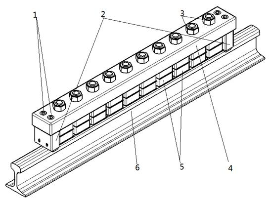
[0025] Such as Figure 1-2 As shown, the electromagnetic rail brake of the present invention is installed in pairs between the two wheels of the bogie on both sides of the rail vehicle, and an electromagnetic rail brake includes a longitudinal beam 4, and the longitudinal beam 4 is other parts and electromagnetic The basic component for connecting or installing the magnetic track brake; the longitudinal beam 4 is located on the upper part of the track 6, parallel to the track 6 and arranged along the longitudinal direction of the track, and the longitudinal space between the track 6 and the longitudinal beam 4 is provided with 2 n ( n ≥2, the same below) electromagnet 5, these 2 n Each electromagnet 5 is distributed along the longitudinal equidistant distance of track 6, and each electromagnet 5 is directly above track 6, and the axial direction of each electromagnet 5 is all vertically perpendicular to track 6 and stringer 4 simultaneously.

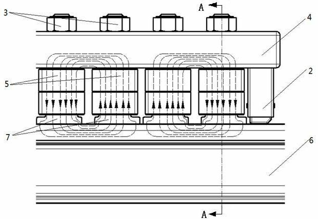
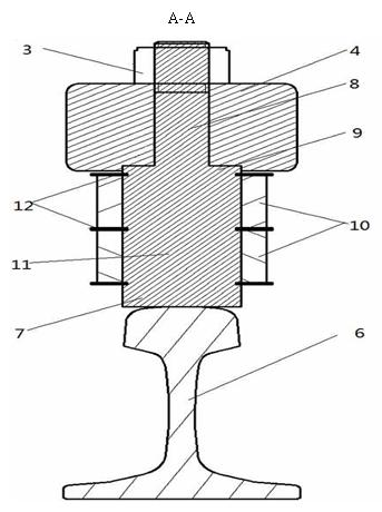
[0026] see Figure 2-6, each ...


PUM

PropertyMeasurementUnit
Vertical spacingaaaaaaaaaa

Abstract

The invention discloses an electromagnetic magnetic rail brake and a control method of the electromagnetic magnetic rail brake. 2n electromagnets distributed in the vertical direction of a rail at equal intervals are arranged between the rail and a vertical beam, each electromagnet respectively consists of a magnetic core and at least two groups of excitation coils, the excitation coils are arranged in the axial direction of the magnetic core and have the same winding modes, the adjacent two electromagnets sequentially form one pair, a closed work magnetic path is formed by each pair of electromagnets, the vertical beam, the rail, and air gaps between each pair of electromagnets and the rail, all of the closed work magnetic paths have loop directions in sequential arrangement at intervals in opposite directions, in addition, axial lines of the closed work magnetic paths are respectively vertical to the vertical direction of the rail, all excitation coils in one closed work magnetic path are respectively connected with the same excitation module, all of the excitation modules are respectively connected with an electronic control unit (ECU), two sets of power supply circuits with a storage battery connected in parallel with a contact network are adopted for control, high braking reliability of high-speed rail vehicles during the emergency braking can be ensured, and the rail vehicles can reliably stop through consuming little energy during the parking.

Description

technical field [0001] The invention relates to an electromagnetic magnetic rail brake and a control method for driving brake and parking and parking thereof, and belongs to the technical field of driving braking and parking and parking of rail vehicles. Background technique [0002] Magnetic rail braking technology is a new type of braking method developed in recent years to adapt to the popularization and high speed of rail vehicles. It mainly relies on the attraction of magnets and rails to generate sliding friction to decelerate rail vehicles. Magnetic rail braking technology mainly includes two types of braking: permanent magnet and electromagnetic. Since the permanent magnet track brake uses permanent magnets, it does not need to consume energy during braking except for manipulation. Compared with permanent magnetic track brakes, electromagnetic track brakes have the characteristics of large braking force, simple maintenance, and convenient operation. [0003] For ma...

Claims


Application Information

Patent Timeline
IPC IPC(8): B61H7/08
Inventor 陈士安顾宇峰何仁王胜陆森林张晓娜姚明武晓晖
Owner 常熟市神龙电动平车有限公司
Why Eureka
Try Eureka