Orthogonal vision detection system for detecting wear condition of end mill

A technology of wear state and orthogonal vision, which is applied in the field of visual inspection system and orthogonal visual inspection system, can solve the problems of imperfect detection of end mills, no effect of thin layer wear on flank face, large calculation error, etc., and achieve automation The effect of high degree, high speed and improved precision

Active Publication Date: 2012-07-11
常州飞石机器人系统有限公司
View PDF3 Cites 40 Cited by
  • Summary
  • Abstract
  • Description
  • Claims
  • Application Information

AI Technical Summary

Problems solved by technology

However, in fact, due to the different processing conditions and the irregular shape of the tool wear area, the calculation error of this method is relatively large.
Lin Lin proposed a scheme to detect rake wear in the article "Image Detection of Rake Face Wear" (Journal of Harbin University of Science and Technology, 2000, Issue 05, page 43), which can effectively detect crater wear on the rake face, but Has no effect on thin layers of wear on the flank
Chi Hui designed a tool wear detection system based on com

Method used


Image

  • Orthogonal vision detection system for detecting wear condition of end mill
  • Orthogonal vision detection system for detecting wear condition of end mill
  • Orthogonal vision detection system for detecting wear condition of end mill

Examples


Example Embodiment

[0025] The specific implementation of the present invention will be further described below in conjunction with the accompanying drawings.

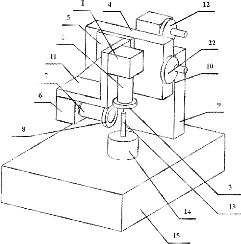
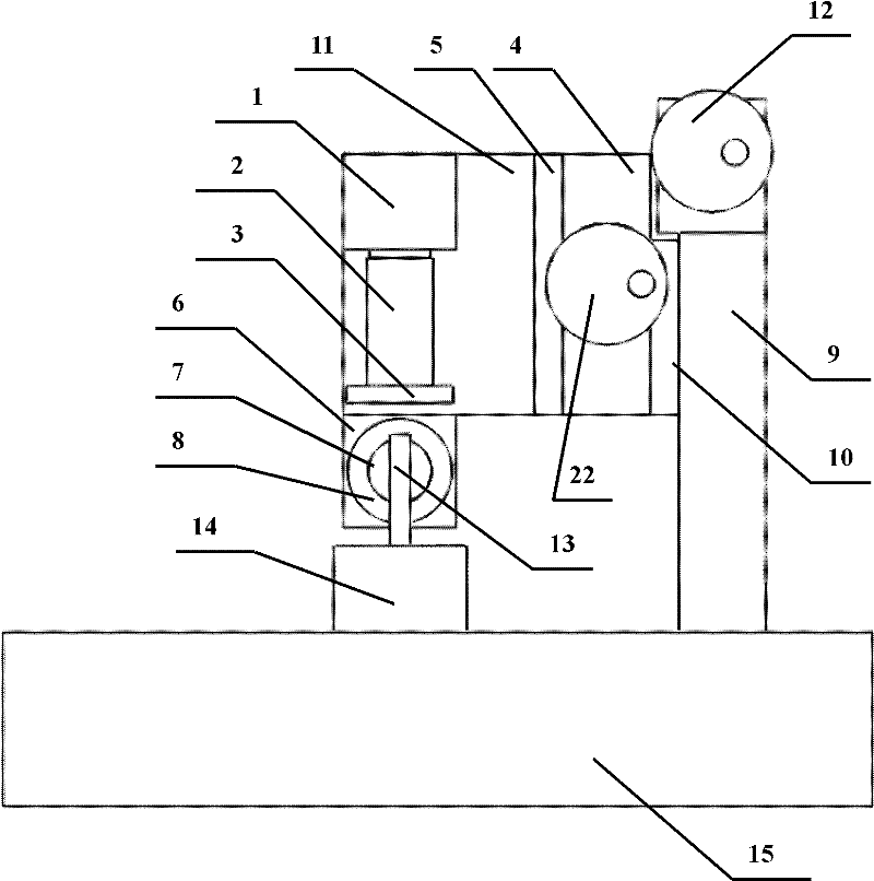
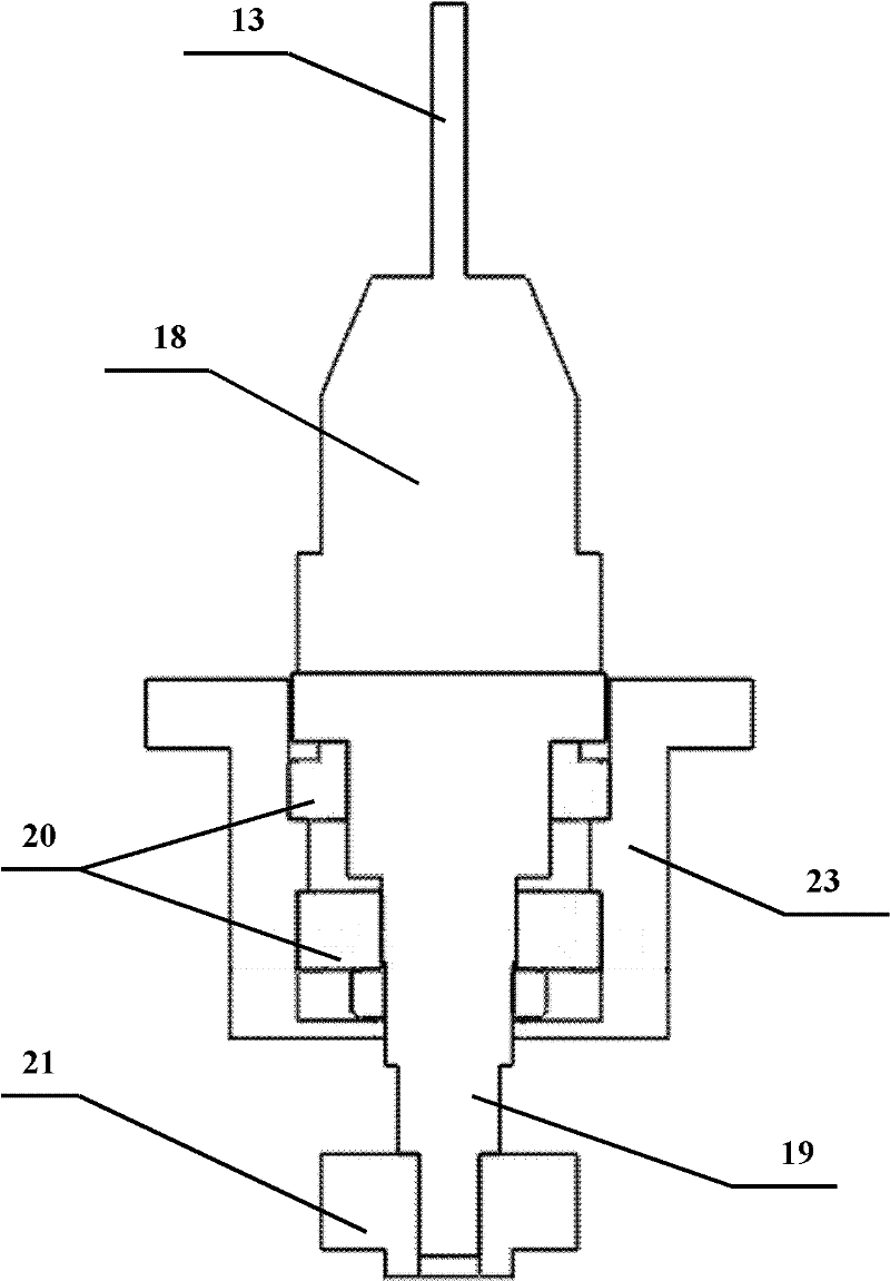
[0026] Such as figure 1 , figure 2 , image 3 , Figure 4 As shown, the present invention includes a top surface CCD camera 1, a top surface lens 2, a top surface ring light source 3, an X-direction guide 4, an X-direction slider 5, a side CCD camera 6, a side lens 7, a side ring light source 8, and a Z direction Guide rail 9, Z-direction slider 10, camera support 11, first hand wheel 12, second hand wheel 22, tool under test 13, rotating table 14, marble base 15, image capture card 16, computer 17. The rotating table 14 is composed of a tool holder 18, a rotating shaft 19, an upper and lower fixed bearing 20, a rotary encoder 21 and a rotating table main body 23.

[0027] The top CCD camera 1 and the side CCD camera 6 are mounted on the camera bracket 11 in orthogonal directions to each other. The camera bracket 11 is L-shaped, and the came...


PUM

PropertyMeasurementUnit
The inside diameter ofaaaaaaaaaa
Outer diameteraaaaaaaaaa
The inside diameter ofaaaaaaaaaa

Abstract

The invention relates to an orthogonal vision detection system for detecting the wear condition of an end mill and belongs to the technical field of optical measurement and mechanical engineering. The orthogonal vision detection system comprises top surface and lateral surface CCD (Charge Coupled Device) cameras, top surface and lateral surface lenses, top surface and lateral surface ring-shaped light sources, an X-directional guide rail, a Z-directional guide rail, an X-directional sliding block, a Z-directional sliding block, a bracket, handwheels, a rotating table, a marble base, an image acquisition card and a computer. According to the invention, the double CCD cameras which are arranged in the orthogonal directions are adopted, an image analog signal of a wear region is acquired by the image acquisition card and is converted into a digital signal, computer-vision software is applied, the digital signal is processed by the computer and the width and the area of a wear zone of a rear tool face of the end mill are accurately measured, so that the detection of the wear condition of the end mill is implemented. The orthogonal vision detection system has the characteristics of non contact, high resolution, high automation degree and high speed. The fault-free operating time of machine tool equipment an be effectively prolonged and the product quality is improved. The orthogonal vision detection system has very important significance and practical value in application of an automatic machine tool.

Description

Technical field: [0001] The invention relates to a visual inspection system for detecting the wear state of an end mill. Especially based on computer vision technology, dual CCD cameras installed in orthogonal directions are used to obtain the image of the wear area of ​​the end mill, which is input into the computer and processed by software to accurately measure the width and area of ​​the wear zone on the flank of the end mill An Orthogonal Vision Inspection System for Detecting the Wear Status of End Mills. It belongs to the technical fields of optical measurement and mechanical engineering. Background technique: [0002] In automated production, an extremely critical technology is tool wear status monitoring technology, which is one of the main means to reduce manufacturing costs, reduce manufacturing environmental hazards, and ensure normal and efficient operation of manufacturing systems and product quality. Studies have shown that the use of tool wear status monito...

Claims


Application Information

Patent Timeline
IPC IPC(8): G01B11/02G01B11/28
Inventor 陈晓波梁伟云习俊通吴卓琦
Owner 常州飞石机器人系统有限公司
Why Eureka
Try Eureka