
Lithography device and method for measuring multi-light spot zero offset

A lithography equipment and zero-position deviation technology, which is applied in the field of integrated circuit equipment manufacturing to achieve the effect of avoiding the zero-position deviation of the light spot

Inactive Publication Date: 2012-07-11
SHANGHAI MICRO ELECTRONICS EQUIP (GRP) CO LTD
View PDF2 Cites 15 Cited by
  • Summary
  • Abstract
  • Description
  • Claims
  • Application Information

AI Technical Summary

Problems solved by technology

However, in actual engineering practice, absolute planes do not exist, and even ultra-flat silicon wafers have fluctuations of more than 100 nanometers

Method used


Image

  • Lithography device and method for measuring multi-light spot zero offset
  • Lithography device and method for measuring multi-light spot zero offset
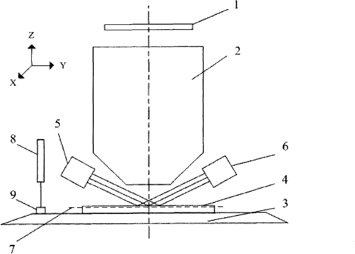
  • Lithography device and method for measuring multi-light spot zero offset

Examples


Embodiment Construction

[0022] Specific embodiments of the present invention will be described in detail below in conjunction with the accompanying drawings.

[0023] The object of the present invention is to provide a lithographic equipment capable of measuring the zero position deviation of multiple spots. The lithographic equipment includes: a light source for providing an exposure light beam. The light source can be a mercury lamp, a laser light source, or other high-brightness light sources, etc. . The projection system is used to project the graphics on the mask onto the substrate, and the projection system can be a total refraction type, reflective type, or catadioptric projection objective lens; the workpiece stage system is used to move the substrate and other A system on a lithographic apparatus that can provide at least 3 degrees of freedom of motion. The focusing and leveling system is used to measure the vertical position and inclination angle of the substrate. The substrate may be a s...


PUM


Abstract

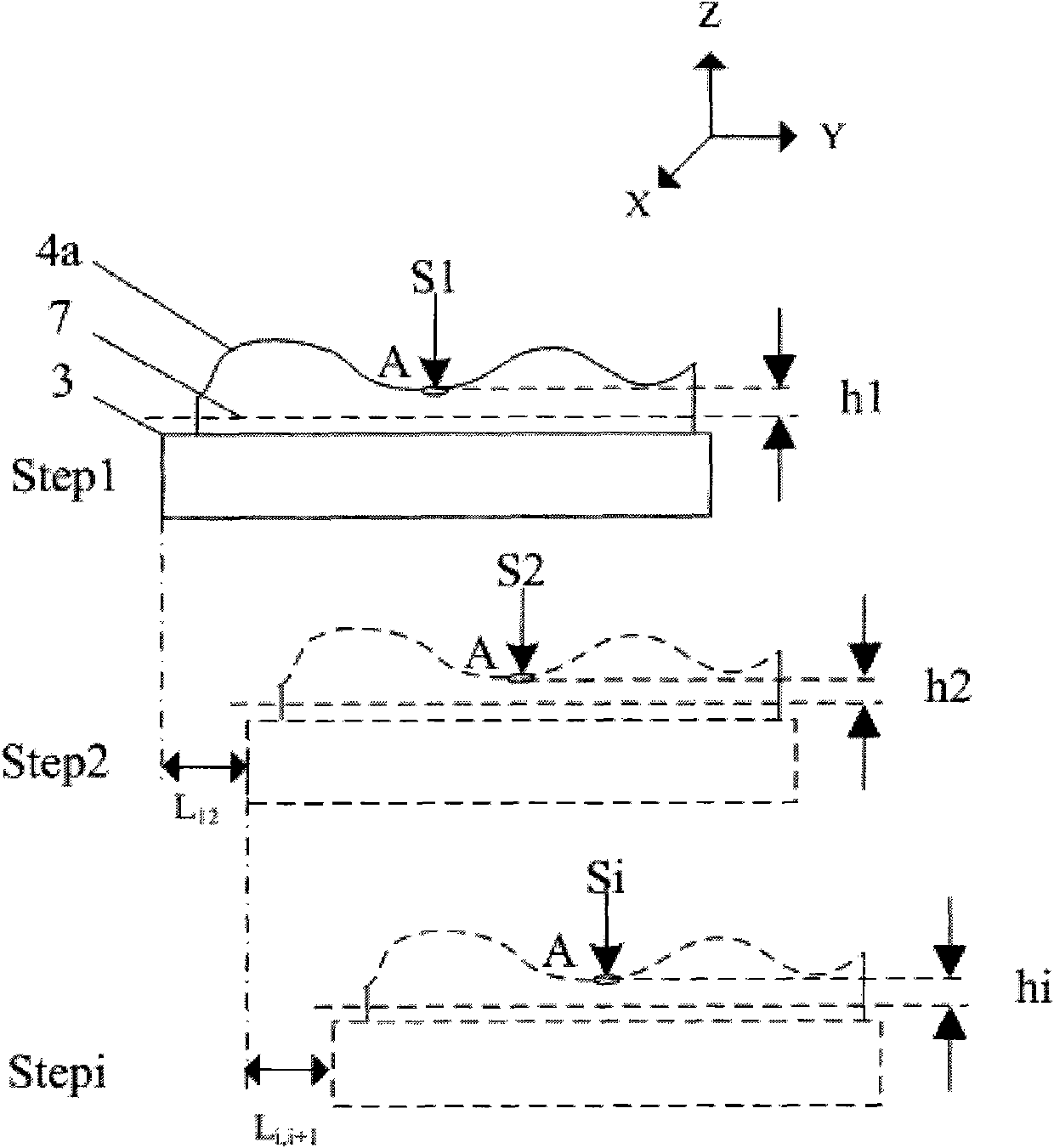
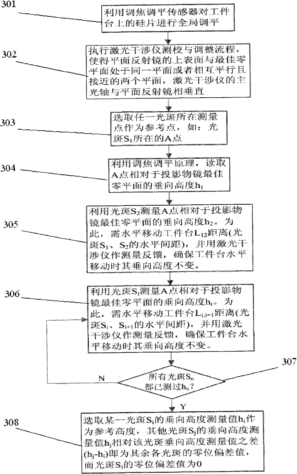
The invention discloses a lithography device, which comprises a light source for providing exposure light beams, a projection system for projecting a pattern on a mask plate onto a substrate, a workbench system for moving the substrate and a focusing leveling system for measuring a vertical position and an inclination angle of the substrate. The lithography device is characterized by further comprising a reflecting mirror and a laser interferometer, wherein the optical axis of the laser interferometer is perpendicular to the reflecting surface of the reflecting mirror, and the reflecting surface of the reflecting mirror is parallel to an optical focal plane of the projection system. The invention further discloses a method for measuring multi-light spot zero offset simultaneously. By means of the method, the multi-light spot zero offset can be accurately measured under the condition of using a normal plane, and influence of the uneven appearance of a measured surface on the height measurement is eliminated.

Description

technical field [0001] The invention relates to the field of integrated circuit equipment manufacturing, in particular to a photolithographic equipment and a method for measuring the zero position deviation of multiple light spots. Background technique [0002] Lithography machine is a kind of equipment used in the manufacture of integrated circuits. The use of this equipment includes but is not limited to: integrated circuit manufacturing lithography equipment, liquid crystal panel lithography equipment, photomask marking equipment, MEMS (micro-electromechanical systems) / MOMS (micro-optical machine system) lithography equipment, advanced packaging lithography equipment, printed circuit board lithography equipment and printed circuit board processing equipment, etc. [0003] In lithography equipment, in order to enable the projection objective lens to clearly project the mask pattern onto the silicon wafer, it is necessary to measure whether the exposure surface of the sil...

Claims


Application Information

Patent Timeline
Patent Type & Authority Applications(China)
IPC IPC(8): G03F7/20G03F9/00
Inventor 魏礼俊陈飞彪李志丹潘炼东
Owner SHANGHAI MICRO ELECTRONICS EQUIP (GRP) CO LTD
Learn More