Compact 35kv side structure of 500kv main transformer

A compact, transformer technology, used in substations, non-enclosed substations, enclosed substations, etc., can solve the problems of occupying land area, large area, large size, etc., to save area, low failure probability, flash The effect of low network probability

Inactive Publication Date: 2012-07-11
HENNAN ELECTRIC POWER SURVEY & DESIGN INST +5
View PDF8 Cites 3 Cited by
  • Summary
  • Abstract
  • Description
  • Claims
  • Application Information

AI Technical Summary

Problems solved by technology

[0013] The shortcomings of conventional dry resistance are also obvious. Its size is relatively large, and it must meet the magnetic shielding distance between them. It is generally arranged in a "shaped" or "shaped" and occupies a large area, such as image 3 , Figure 4 , Figure 5 and Image 6 As shown in the figure, the dotted line box of the reactor indicates the magnetic shielding distance
[0014] Conventional capacitor complete sets are arranged in separate phases in substations, resulting in a large footprint, such as Figure 7 , Figure 8 shown
In the figure, each phase reactor is installed on a tower, and each phase reactor is divided into two sections. This arrangement occupies a large amount of land area

Method used


Image

  • Compact 35kv side structure of 500kv main transformer
  • Compact 35kv side structure of 500kv main transformer
  • Compact 35kv side structure of 500kv main transformer

Examples


Embodiment 1

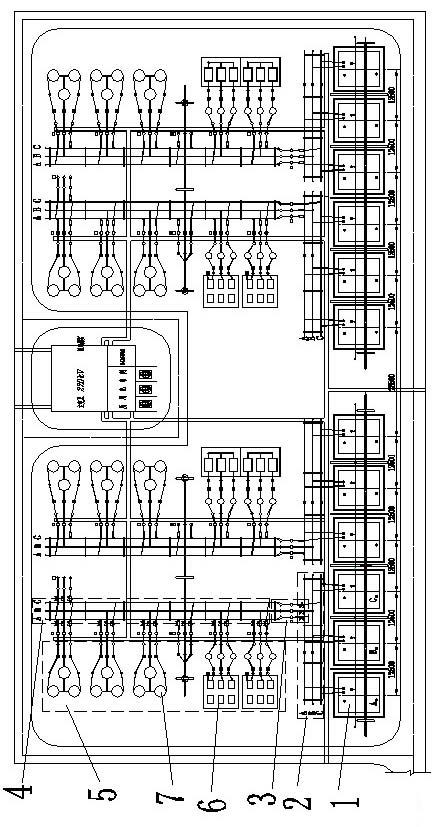
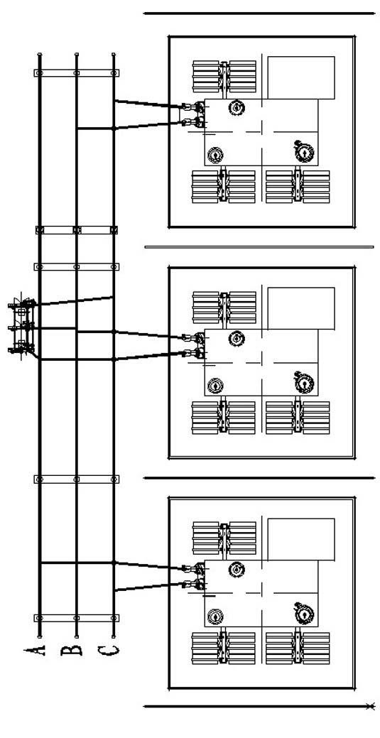
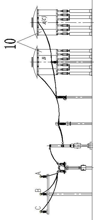
[0071] like Figure 9 As shown, the present invention comprises A, B, C three-phase transformer 1, and three-phase transformer 1 connects total circuit 3 through △ bus 2, and total circuit 3 connects 35kv bus 4, and 35kv bus 4 connects each branch circuit 5, and above-mentioned branch circuit It includes a capacitive branch circuit 6 and a reactance branch circuit 7 . The capacitance branch circuit 6 includes a parallel capacitor bank 8 and a series reactor 9 connected to the parallel capacitor bank 8 ; the reactance branch circuit 7 includes a three-phase reactor 10 . In order to realize the compact design, the present invention adopts the dry-type insulated bus bar 2 to complete the △ winding; in the capacitance branch circuit 6, the A, B, and C three-phases in each parallel capacitor bank are superimposed and placed; in the reactance branch circuit In 7, the reactor 10 is a stacked dry-type shunt air-core reactor or a magnetic shield shunt reactor, which will be specifical...

Embodiment 2

[0088] The difference between this embodiment and Embodiment 1 is that in the reactance branch circuit 7 of this embodiment, as Figure 14 As shown, the stacked dry-type shunt air-core reactor refers to: A, B, C three-phase reactors are stacked up and down, and reactance post insulators 13 are arranged between adjacent two-phase reactors.

Embodiment 3

[0090] The difference between this embodiment and Embodiment 1 and Embodiment 2 is that in the reactance branch circuit 7 of this embodiment, a magnetically shielded shunt reactor is used.

[0091] like Figure 15 --As shown in 18, this embodiment includes reactors connected in parallel with three phases A, B, and C. Each of the above-mentioned reactors is composed of upper and lower sections, and the upper and lower sections of each phase reactor are connected through a star The frame 12 is connected; and the wire package 16 of each section of reactor is provided with a high-permeability magnetic core inside and outside.

[0092] It should be noted that the structure of the upper and lower parts of each phase reactor is basically the same, which is a concentric circle structure composed of multi-layer wire wraps. The inner iron core 17 and the outer iron core 18 are arranged inside and outside, so that the reluctance of the reactor is greatly reduced, and at the same time it ...


PUM


Abstract

The invention relates to a compact 35kv side structure of a 500kv main transformer, which comprises an A, B, C three-phase transformer which is connected with a main circuit by a triangular bus, the main circuit is connected with a 35kv bus which is connected with all branch circuits, and each branch circuit comprises a capacitance branch circuit and a reactance branch circuit; the capacitance branch circuit comprises a parallel capacitor set and a serial rector connected with the parallel capacitor set; the reactance branch circuit comprises a three-phase reactor; the triangular bus adopts a dry insulated bus for accomplishing a triangular winding; A, B, C three phases are overlaid in each parallel capacitor set in the capacitance branch circuit; and in the reactance branch circuits, the reactors are piled dry parallel air-core reactors or magnetic-shielding parallel reactors.

Description

technical field [0001] The invention relates to a compact 500kv main transformer 35kv side structure. Background technique [0002] my country's 500kv substation adopts 550kv / 220kv / 35kv three-level voltage, and the low-voltage side is connected to reactive power compensation device and station power, which is an important part of the substation. [0003] At present, in the design of substations, the design optimization of high voltage levels is generally emphasized. By optimizing the wiring type, adopting compact equipment, and reducing the size of power distribution devices, the reliability of the substation is improved, the floor area is reduced, and the project cost is reduced. However, the original ideas and models are still continued for the low-voltage side of the main transformer, and conventional equipment and conventional power distribution devices are used. There has been no obvious development and change over the years, and it occupies a large area. In the substa...

Claims


Application Information

Patent Timeline
Patent Type & Authority Applications(China)
IPC IPC(8): H02B5/00H02B7/00H02B1/20H02B1/04H02J3/18
CPCY02E40/30
Inventor 冯蕾王伟杨光曹志民张继军顾尔重徐荥王健
Owner HENNAN ELECTRIC POWER SURVEY & DESIGN INST
Why Eureka
Try Eureka