Electric corrosion prevention rotor and production method thereof

A technology of anti-electrocorrosion and rotor, which is applied in the manufacture of stator/rotor body, magnetic circuit rotating parts, shape/style/structure of winding insulation, etc. It can solve the problem of shortening the service life of bearings, accelerating wear speed, and the material of inner and outer rings of bearings. Hardness reduction and other problems, to achieve the effect of improving the service life of the bearing, preventing axial or radial movement, and preventing electric corrosion of the bearing

Active Publication Date: 2012-07-11
WOLONG ELECTRIC GRP CO LTD +1
View PDF8 Cites 2 Cited by
  • Summary
  • Abstract
  • Description
  • Claims
  • Application Information

AI Technical Summary

Problems solved by technology

The current breaks down the oil film discharge between the bearing balls and the inner and outer rings, resulting in high temperature, causing the local surface of the bearing to melt, forming spots ...

Method used


Image

  • Electric corrosion prevention rotor and production method thereof
  • Electric corrosion prevention rotor and production method thereof
  • Electric corrosion prevention rotor and production method thereof

Examples


Embodiment 1

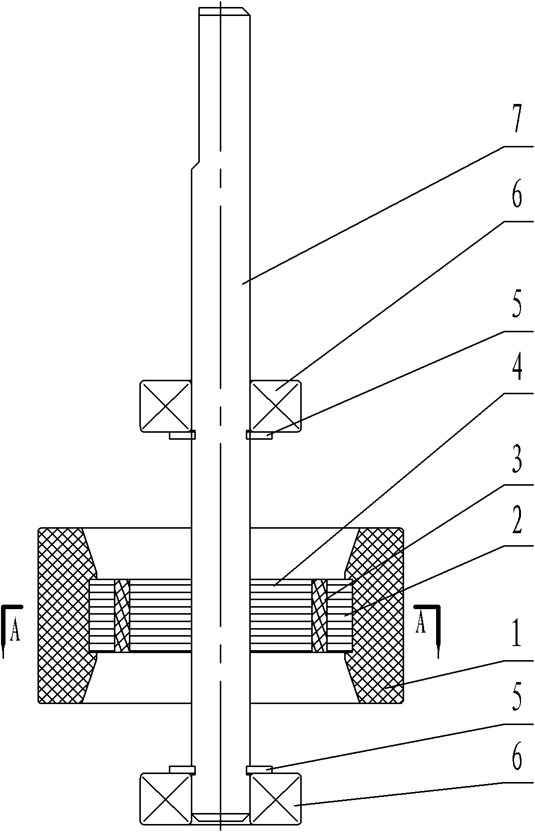
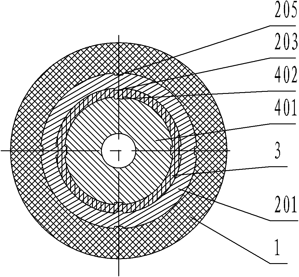
[0033] like figure 1 , 2 As shown, the present invention includes a rotating shaft 7, an iron core sleeved on the rotating shaft 7, and a magnet 1 externally arranged on the iron core. The core 4 is concentric with the outer yoke core 2 , and an insulating frame 3 is provided between the inner yoke core 4 and the outer yoke core 2 . The inner yoke core 4 is formed by stacking several inner yoke core punches 401; the outer yoke core 2 is formed by stacking several outer yoke core punches 201; the first insulating skeleton of the inner yoke core punches 401 The positioning portion 403 is opposite to the second insulating frame positioning portion 203 of the outer yoke core punching piece 201 of the same layer. The magnet 1 is covered on the outer peripheral surface and the upper and lower end surfaces of the outer yoke core 2 .

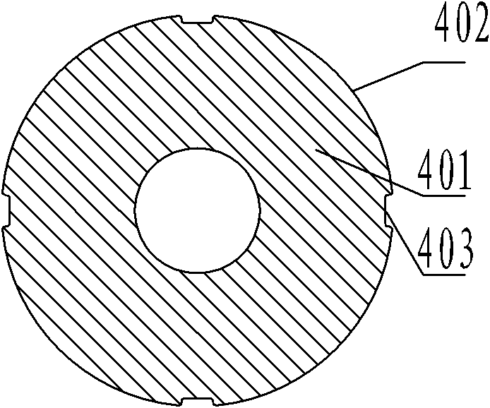
[0034] like image 3 As shown, the inner yoke iron core punching piece 401 is in the shape of a ring, the middle of which is a through hole for pas...

Embodiment 2

[0043] Embodiment 2: The same parts as Embodiment 1 will not be repeated. The difference lies in that the first insulation frame positioning parts 403 of the outer yoke core punches 201 of adjacent layers are aligned and stacked.

Embodiment 3

[0044] Embodiment 3: The first insulating frame positioning side 402 of the inner yoke iron core punching piece 401 is provided with five evenly distributed first insulating frame positioning parts 403, and the first insulating frame positioning parts 403 protrude from the first insulating frame positioning The edge 402 forms a convex point; the wall of the insulating hole 202 of the outer yoke iron core punching piece 201 is provided with four evenly distributed second insulating skeleton positioning parts 203, and the second insulating skeleton positioning part 203 is recessed in the wall of the insulating hole 202 to form a groove. The magnet positioning side 204 of the outer yoke core punching piece 201 is provided with four evenly distributed magnet positioning parts 205 , and the magnet positioning parts 205 protrude from the magnet positioning side 204 .


PUM


Abstract

The invention discloses an electric corrosion prevention rotor and a production method thereof, and relates to a direct current high-voltage plastic package motor rotor and a production method thereof. At present, the electric corrosion phenomenon is normal for a direct current plastic package motor; an oil membrane is broken down by current between a bearing ball and an inner ring as well as an outer ring to discharge to produce high temperature, so that local surface of a bearing is melted to form spots and pits, and further, the hardness of the material of the inner ring and the outer ring of the bearing is reduced. The rotor comprises a rotating shaft, an iron core and a magnet, wherein the iron core is sleeved on the rotating shaft; the magnet is arranged outside the iron core; the rotor is characterized in that: the iron core comprises an inner yoke iron core and an outer yoke iron core which is arranged at the periphery of the inner yoke iron core and is concentric with the inner yoke iron core; and an insulating framework is arranged between the inner yoke iron core and the outer yoke iron core. According to the technical scheme, a current loop is cut off through the insulating framework which is arranged between the rotor inner yoke iron core and the rotor outer yoke iron core, so that the axial current flows to the bearing through the rotating shaft, and further, the electric corrosion of the bearing is effectively prevented, and the service life of the bearing of the direct current high-voltage plastic package motor is prolonged.

Description

technical field [0001] The invention relates to a DC high-voltage plastic-sealed motor rotor and a production method thereof. Background technique [0002] Galvanic corrosion is common in DC plastic-sealed motors, which is caused by current discharge. The existing DC plastic-sealed motors have insulating materials between the end cover and the stator core, and the end cover and the iron core are completely insulated. When the stator coil passes through When the voltage is modulated at high frequency, due to the coupling effect, a voltage difference is formed between the stator core and the metal end cover, and the current forms a loop through the metal part of the rotor, the inner and outer rings of the bearing, and the end cover matching the bearing. The current breaks down the oil film discharge between the bearing balls and the inner and outer rings, resulting in high temperature, which causes the local surface of the bearing to melt, forming spots and pits, resulting in ...

Claims


Application Information

Patent Timeline
IPC IPC(8): H02K1/27H02K3/34H02K15/03
Inventor 杜荣法张健翟德虎王建华张龙体张亚超
Owner WOLONG ELECTRIC GRP CO LTD
Why Eureka
Try Eureka