
Hole pitch error correction system for numerical control multi-spindle deep hole drilling machine

A technology of error correction and deep hole drilling machine, which is applied in drilling/drilling equipment, parts of boring machine/drilling machine, measurement of positioning in boring machine/drilling machine, etc. Accuracy and cumulative accuracy, multi-axis deep hole drilling machine hole spacing accuracy is not high, etc.

Inactive Publication Date: 2012-07-18
上海悦英机械设备制造限公司
View PDF0 Cites 0 Cited by
  • Summary
  • Abstract
  • Description
  • Claims
  • Application Information

AI Technical Summary

Problems solved by technology

[0002] It can be seen from the existing data that the accuracy of the hole pitch of the multi-axis deep hole drilling machine is not high. For example, the nuclear power evaporator tube plate with the number of holes up to 3000mm to 10000, the hole diameter of 12mm to 32mm, and the hole depth of 1000mm is processed by a three-axis deep hole drilling machine. It is difficult to meet the requirements of adjacent accuracy and accumulative accuracy of ≤0.10mm for the hole distance of the cutting surface of the tube plate. For example, the BW500-3-1800-CNC CNC three-axis deep hole drilling machine of the German KOLB company, which is internationally representative, is difficult to achieve For this requirement, only two drilling spindles can be used to process

Method used


Image

  • Hole pitch error correction system for numerical control multi-spindle deep hole drilling machine
  • Hole pitch error correction system for numerical control multi-spindle deep hole drilling machine
  • Hole pitch error correction system for numerical control multi-spindle deep hole drilling machine

Examples


Embodiment Construction

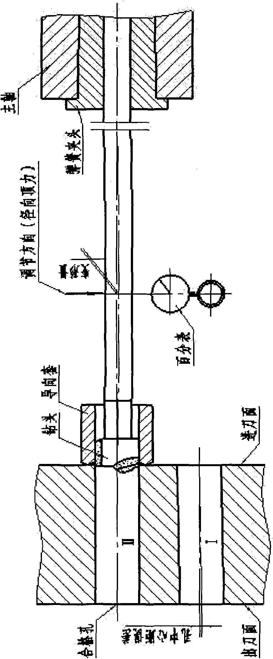
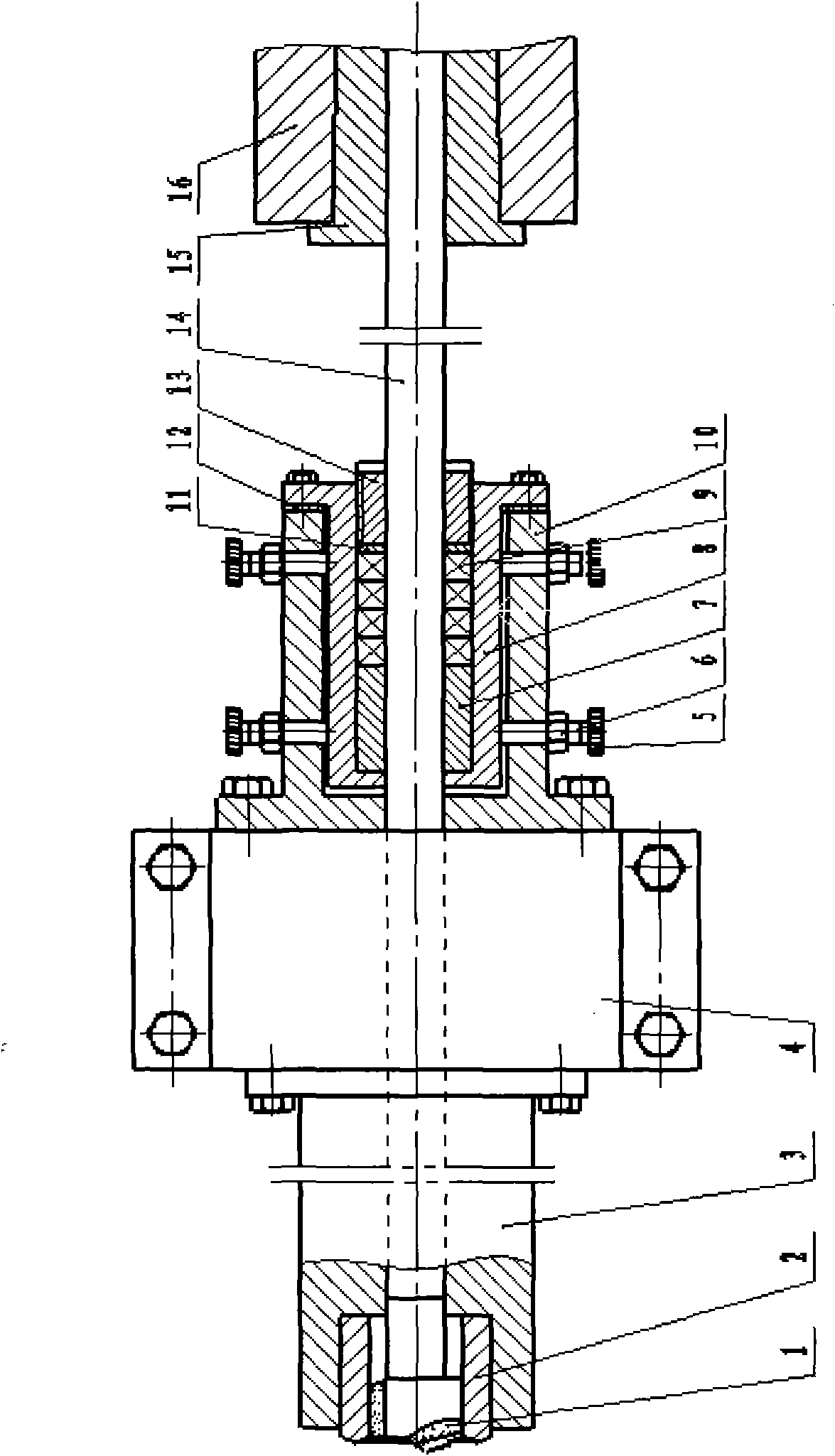
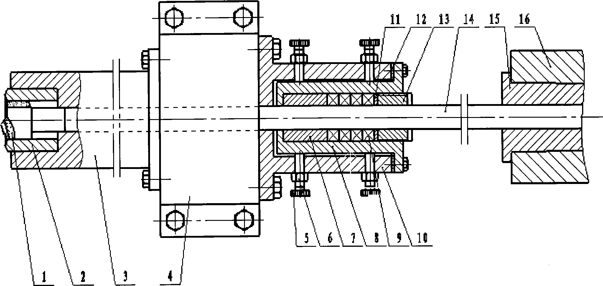
[0007] like figure 1 Shown: When the force of the fine-tuning screw acts on the drill pipe, the drill pipe will produce a slight downward bending elastic deformation. The position inside the sleeve should have a slight offset from the original position. When the drill moves axially to the exit surface of the workpiece, the offset just compensates the error value of the distance between the exit surface and the hole. In fixed jacket 10 [see figure 2 〕There are 4 or 8 fine-tuning screws evenly distributed on the circumference, and one or two rows are arranged according to the size of the drill pipe (that is, the aperture). The use of any fine-tuning screw and its force should be based on the hole distance error and the offset direction To decide.

[0008] like figure 2 As shown, the clamp body 4 fixed on the guide rail of the machine tool is fixed on the left end of the long sleeve 3 and the guide sleeve 2; the right end is fixed on the outer sleeve 10, 4 or 8 fine-tuning s...


PUM


Abstract

The invention relates to a drill spindle system for a multi-spindle deep hole drilling machine. Errors of a plurality of drill spindles for drilling deep holes are corrected by means of mechanical elastic deformation principle. The drill spindle system is characterized in that a drill rod slightly bends and elastically deforms when the acting force of a fine adjustment screw acts at the center of the drill rod, the deformation of the drill rod is determined by means of calculation according to the hole pitch error value of a tool discharge surface of a drilled workpiece (namely the back surface of the workpiece), the position of a drill bit in a drill bushing is slightly shifted relative to an original position at the moment, and the offset value of the drill bit exactly compensates the hole pitch error value of the tool discharge surface when the drill bit axially moves to the tool discharge surface of the workpiece in a drilling manner. The drill rod reliably and axially moves in a drilling manner through a guide sleeve of an embedded structure, holes of different sizes can be machined by changing drill bits, drill rods and buttress sleeves of different sizes, and the hole pitch error correction system enables the drill spindles of the multi-spindle deep hole drilling machine to simultaneously drill 1000mm deep holes with extremely small adjacent hole pitch errors and accumulated hole pitch errors.

Description

technical field [0001] The patent of the present invention relates to a hole pitch error correction system of a CNC multi-axis deep hole drilling machine, especially when the drill shaft drills deep holes, the method of elastically deforming the drill rod is adopted, and the axial cutting movement is guided by a special drill sleeve, and the composition is composed of A multi-axis deep hole drilling machine hole distance error correction system is proposed. Background technique [0002] It can be seen from the existing data that the accuracy of the hole pitch of the multi-axis deep hole drilling machine is not high. For example, the nuclear power evaporator tube plate with a number of holes up to 3000mm to 10000, a hole diameter of 12mm to 32mm, and a hole depth of 1000mm is processed by a three-axis deep hole drilling machine. It is difficult to meet the requirements of adjacent accuracy and accumulative accuracy of ≤0.10mm for the hole distance of the cutting surface of th...

Claims


Application Information

Patent Timeline
IPC IPC(8): B23B49/00
Inventor 戴励群陈岳兴黎永明
Owner 上海悦英机械设备制造限公司
Learn More