

Wavelength scanning interferometer and method for aspheric measurement
A technology of wavelength scanning and aspheric surface, which is applied in the direction of measuring device, measuring optics, reflective surface testing, etc.
- Summary
- Abstract
- Description
- Claims
- Application Information
AI Technical Summary
Problems solved by technology
Method used
Image

Examples
Embodiment 1
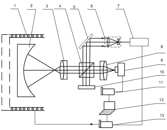
[0026] figure 1 It is the system schematic diagram of the wavelength scanning interferometer used for aspheric surface measurement of the present invention. Such as figure 1 As shown, the wavelength scanning interferometer and method for measuring aspheric surfaces of the present invention include a translation stage 1, a measured aspheric surface 2, a first mirror group 3, a beam splitter 4, a plane mirror 5, a beam expander mirror 6, and a tunable laser 7 , imaging lens 8, CCD camera 9, reference plane mirror 10, image card 11, computer 12 and data card 13. Among them, the measured aspheric surface 2 is fixed on the translation stage 1, the measured aspheric surface 2, the first mirror group 3, the beam splitter 4, the imaging lens 8 and the CCD camera 9 are placed coaxially in sequence, and the plane mirror 5 and the reference plane mirror 10 are respectively placed on the The bottom and top of the beam splitter 4, the CCD camera 9, the image card 11, the computer 12 an...
Embodiment 2
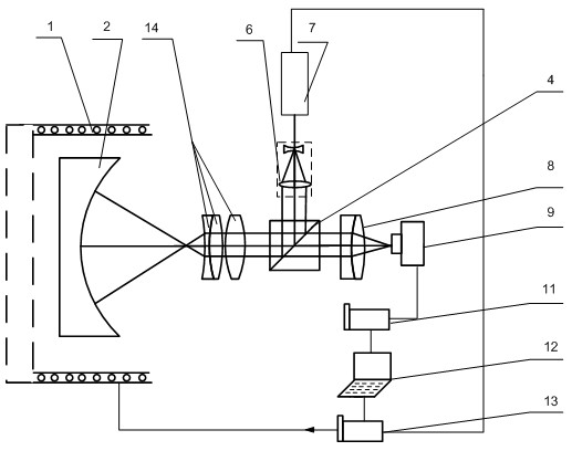
[0030] figure 2 It is another system schematic diagram of the wavelength-scanning interferometer used for aspheric surface measurement of the present invention. It takes the form of a Fizeau interferometer. and figure 1The difference is that the reference beam is formed by Fresnel reflection of the last surface of the second mirror group 14 (the leftmost surface of the second mirror group in the figure). The light beam emitted from the tunable laser 7 becomes a parallel beam after being expanded by the beam expander 6, and a part thereof is reflected by the beam splitter 4 to the second mirror group 14, and the last surface of the second mirror group 14 is not coated with an anti-reflection coating, so Part of the incident light will be reflected back to the beam splitter 4, and the other part will be focused by the second lens group 14 and then incident on the measured aspheric surface 2 and be reflected back. The two parts of light are superimposed on the beam splitter ...
PUM
 Abstract
Description
Claims
Application Information