Photorefractive long-period waveguide grating filter and manufacturing method thereof

A technology of waveguide grating and manufacturing method, which is applied in the direction of optical waveguide lightguide, coupling of optical waveguide, cladding optical fiber, etc., can solve the problems of low material reuse rate, difficult manufacture, complex structure of grating filter, etc., and achieve improved reuse efficiency, device and process are simple, and the effect of simple manufacturing technology

Inactive Publication Date: 2012-07-18
ZHEJIANG UNIV OF TECH
View PDF3 Cites 21 Cited by
  • Summary
  • Abstract
  • Description
  • Claims
  • Application Information

AI Technical Summary

Problems solved by technology

[0006] In order to overcome the deficiencies of the existing grating filter such as complex structure, difficult manufacture and low material reutilization rate, the present invention p

Method used


Image

  • Photorefractive long-period waveguide grating filter and manufacturing method thereof
  • Photorefractive long-period waveguide grating filter and manufacturing method thereof
  • Photorefractive long-period waveguide grating filter and manufacturing method thereof

Examples


Embodiment 1

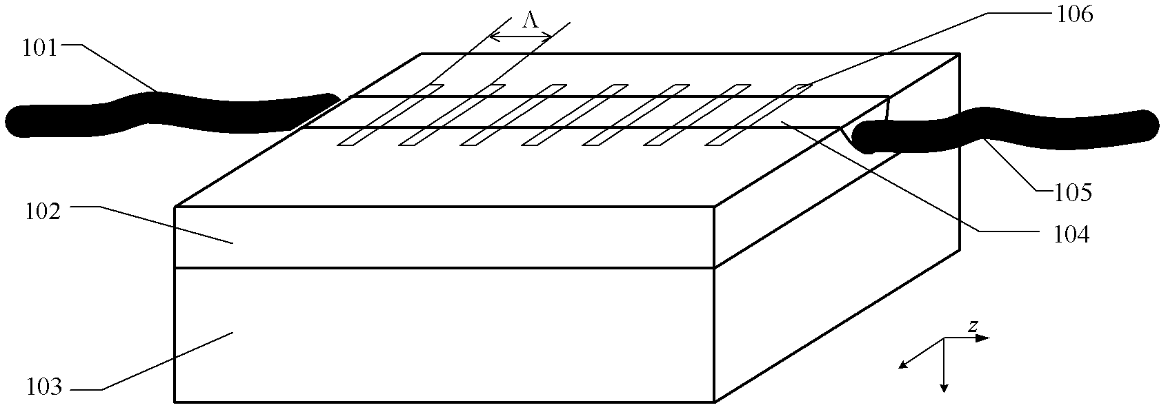
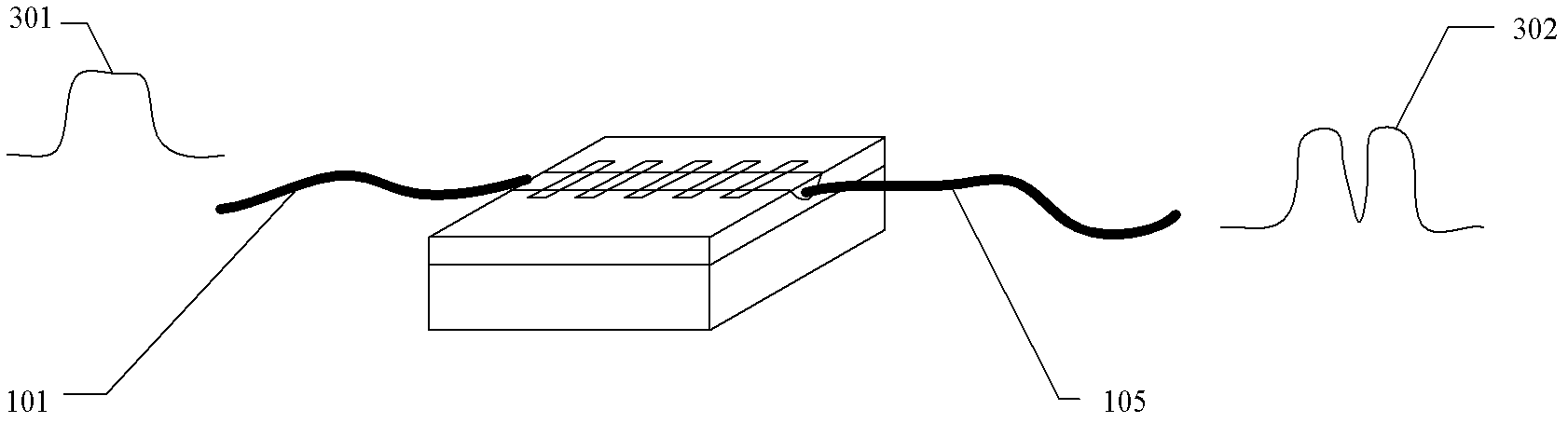
[0032] refer to Figure 1 ~ Figure 3 , a photorefractive long-period waveguide grating filter, including an input pigtail 101 and an output pigtail 105, the photorefractive long-period waveguide grating filter also includes a photorefractive long-period waveguide grating, the photorefractive The long-period waveguide grating includes a substrate 103, which is X- or Y-cut Z-propagated LiNbO 3 A cladding layer 102 is arranged on the substrate 103, and a single-mode waveguide 104 arranged in the Z direction is arranged on the cladding layer 102. A photorefractive holographic grating 106 is fabricated on the single-mode waveguide 104, and the 104 of the single-mode waveguide The two end faces are respectively connected to the input pigtail 101 and the output pigtail 105 .

[0033] Two end surfaces of the single-mode waveguide 104 are glued and fixedly connected to the input pigtail 101 and the output pigtail 105 respectively.

[0034] The geometric dimensions, guided mode parame...

Embodiment 2

[0037] refer to Figure 1 ~ Figure 3 , the difference between this embodiment and Embodiment 1 is that the input pigtail 101 and the output pigtail 105 are respectively added to the two ends of the successful photorefractive variable-period waveguide grating to form a photorefractive variable-period Waveguide grating filter. After the pigtails 101 and 105 are fixed by a clamp, they are directly aligned and adhered to the end surface of the waveguide. Other structures and implementations of this embodiment are completely the same as those of Embodiment 1.

Embodiment 3

[0039] refer to Figure 1 ~ Figure 3 , a method for manufacturing a photorefractive long-period waveguide grating filter, comprising the following steps:

[0040] Step 1 Fabrication of lithium niobate substrate single-mode waveguide

[0041] refer to figure 1 , the waveguide used in the present invention is based on a lithium niobate crystal 103, through the first expansion of titanium to form a cladding 102, and then through the second expansion of titanium to form a waveguide 104; the grating 106 made on the waveguide is a photorefractive holographic raster.

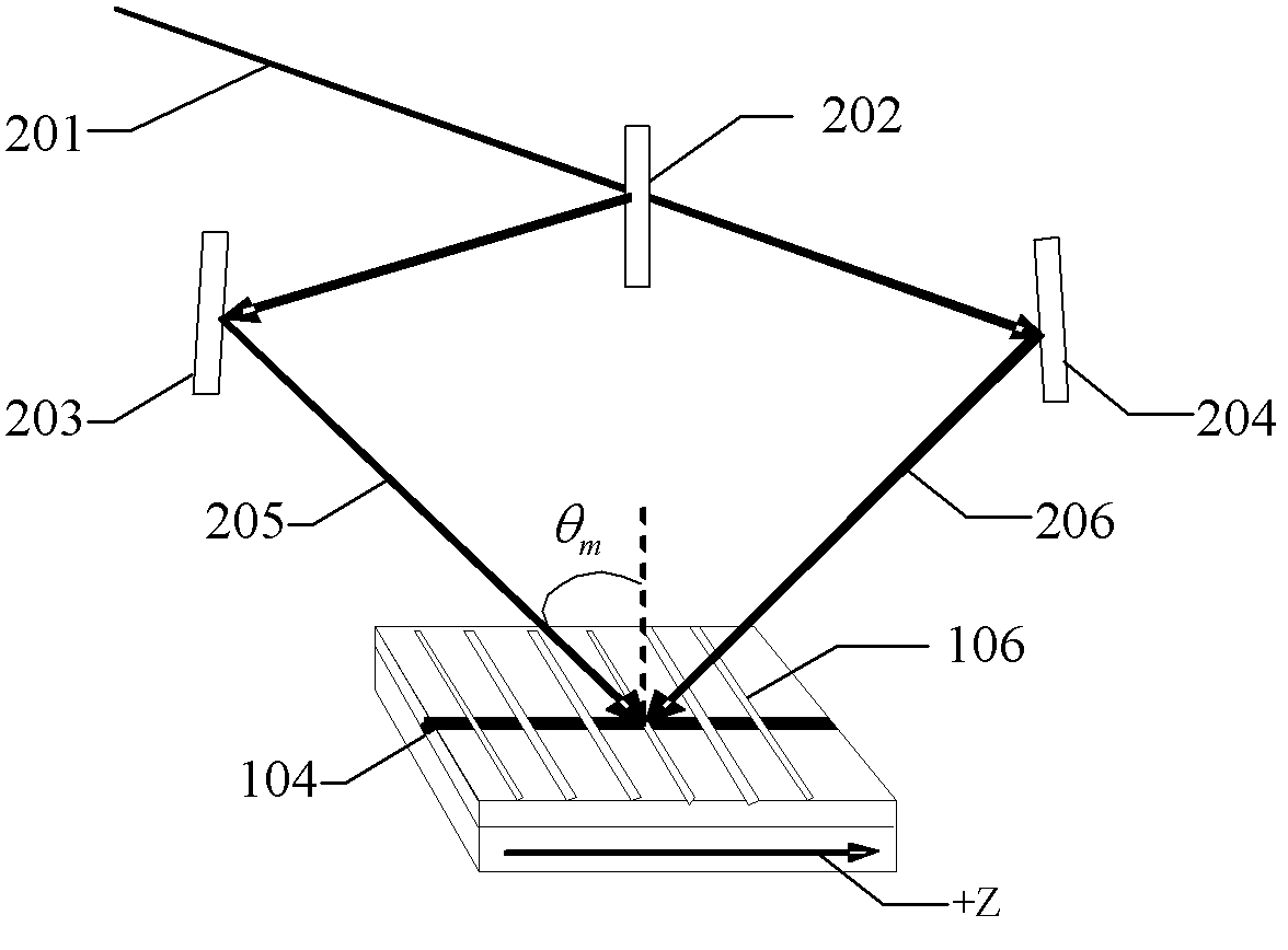
[0042] Step 2 Fabrication of photorefractive long-period waveguide grating

[0043] refer to figure 2, the recording laser 201, preferably, can be an argon ion laser, or a 532nm frequency-doubled Nd:YAG laser, which is divided into two beams of light by a beam splitter 202, one of which is reflected by a reflector 203 to form a path of interference light 205 incident to the lithium niobate waveguide 104. Another...


PUM


Abstract

The invention relates to a photorefractive long-period waveguide grating filter, which comprises input tail fiber and output tail fiber. The photorefractive long period waveguide grating filter further comprises a photorefractive long period waveguide grating that comprises a substrate. The substrate is a LiNbO3 crystal that is tangential in X or Y direction and conductive in Z direction and a cladding is arranged on the substrate. A Z-directional single mode waveguide is arranged on the cladding. A photorefractive holographic grating is manufactured on the single mode waveguide. Two end surfaces of the single mode waveguide are respectively connected with the input tail fiber and the output tail fiber. The invention further provides a manufacturing method of the photorefractive long-period waveguide grating filter. The photorefractive long-period waveguide grating filter has a simplified structure, is convenient to manufacture and has higher recycle rate of materials.

Description

technical field [0001] The invention relates to the field of integrated optics and the field of optical communication passive devices, in particular to a photorefractive long-period waveguide grating filter and a manufacturing method thereof. Background technique [0002] The function of the grating filter is to select the optical signal of a specific wavelength according to the needs among the input optical signals of multiple wavelengths. It is a key node device for realizing large-capacity and high-speed all-optical network communication. application. [0003] Optical filters based on grating structures can be divided into Bragg grating optical filters and long-period grating optical filters according to their grating periods. The Bragg grating filter exhibits band-rejection characteristics. The central wavelength of reflection is the Bragg wavelength, and the Bragg wavelength satisfies λ=2nΛ, n represents the average refractive index of the fiber core (waveguide), and Λ...

Claims


Application Information

Patent Timeline
IPC IPC(8): G02B6/34G02B6/02G02B6/13
Inventor 张明陈刘伟王东旭乐孜纯
Owner ZHEJIANG UNIV OF TECH
Why Eureka
Try Eureka