
Temperature sensing system for rapid temperature program

A technology of temperature sensing circuit and temperature sensing, which is applied in the direction of radiation pyrometry, measuring device, electric radiation detector, etc., can solve the problems affecting the production of light absorbing layer, affecting the production quality of photovoltaic modules, and incomplete temperature data, etc.

Inactive Publication Date: 2012-07-25
SOLAR ENERGY TECH
View PDF6 Cites 2 Cited by
  • Summary
  • Abstract
  • Description
  • Claims
  • Application Information

AI Technical Summary

Problems solved by technology

However, the placement position of the thermocouple is limited, it can only be placed on the edge of the glass substrate and cannot be placed in the middle of the glass substrate or in the area where the light absorbing layer is made, otherwise it will affect the making of the light absorbing layer
However, only placed on the edge of the glass substrate can only detect the temperature of the edge, and cannot detect the temperature of any area of ​​the glass substrate, so the measured temperature data is incomplete, and the temperature controlled by the RTP program is Can not be correct, which will affect the production quality of photovoltaic modules
Therefore, the temperature measurement technology using thermocouples is not the best temperature measurement technology when making photovoltaic modules
[0006] In addition, although the temperature measurement technology using an infrared pyrometer is a non-contact technology, because it mainly detects the infrared rays radiated from the object to be measured (ie, the glass substrate), the heating component in the RTP program is very sensitive to The heat source emitted by the glass substrate also contains a large amount of infrared rays. Therefore, when detecting the infrared rays of the glass substrate, it will be greatly interfered by the infrared rays emitted by the heating element, making the measured temperature data inaccurate. The same will affect to the production quality of photovoltaic modules
Therefore, the temperature measurement technology using an infrared pyrometer is not the best temperature measurement technology when making photovoltaic modules

Method used


Image

  • Temperature sensing system for rapid temperature program
  • Temperature sensing system for rapid temperature program
  • Temperature sensing system for rapid temperature program

Examples


Embodiment Construction

[0015] In order to describe the technical characteristics of the present invention in detail, the following preferred embodiments are cited and described as follows in conjunction with the accompanying drawings, wherein:

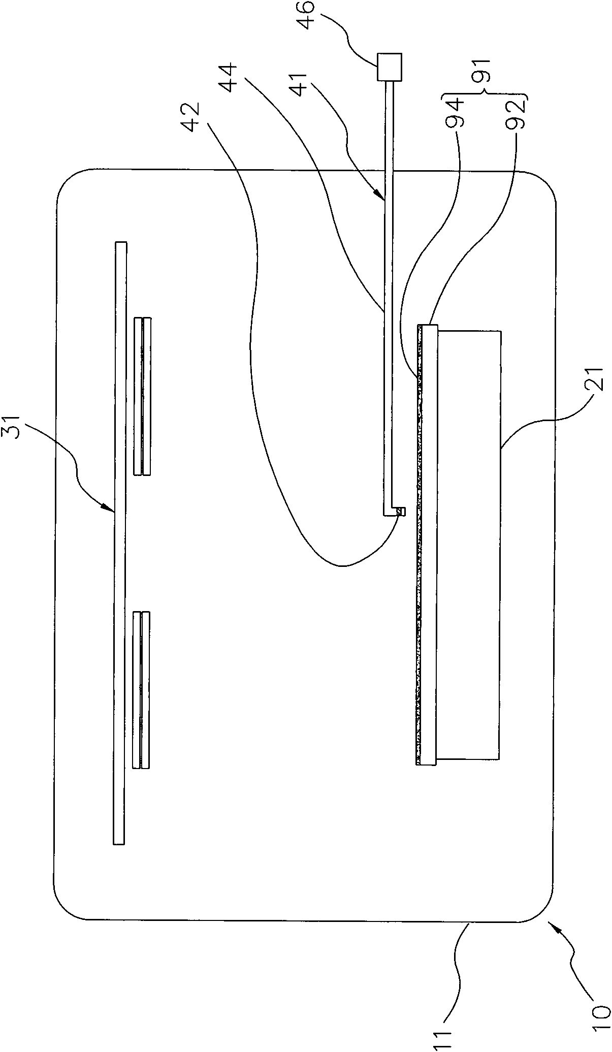
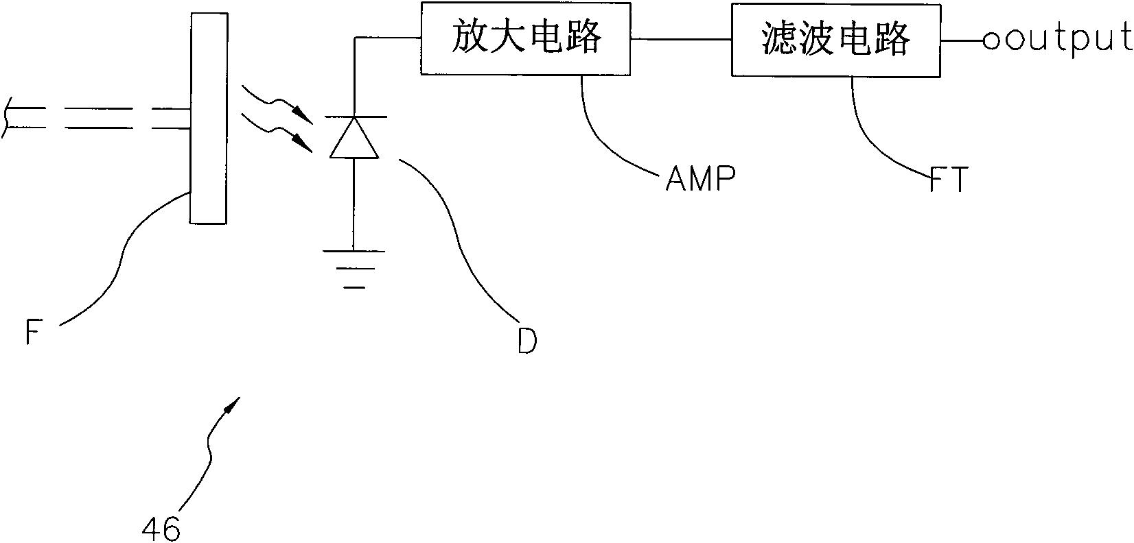
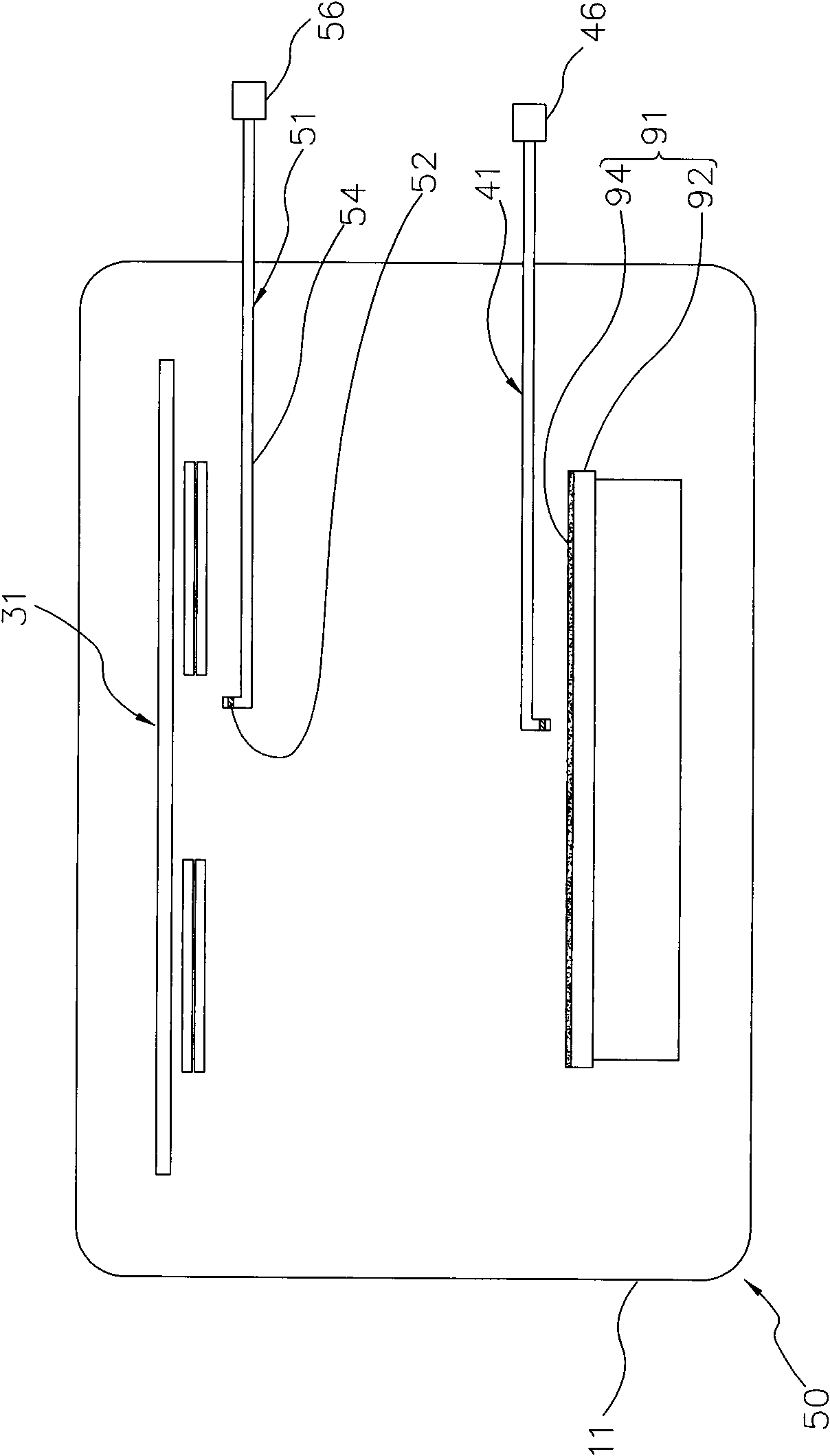
[0016] Such as Figure 1 to Figure 2 As shown, a temperature sensing system 10 used in a rapid temperature program provided by the first preferred embodiment of the present invention mainly consists of a chamber 11, a platform 21, a heat source 31 and a black body temperature detector 41 consisting of:

[0017] The rapid temperature program is used for heating a photovoltaic module intermediate product 91. In this embodiment, the photovoltaic module intermediate product 91 has a substrate 92 and at least one layer that is coated on the upper surface of the substrate 92 and is being formed. light absorbing layer 94 . In this embodiment, the substrate 92 is made of glass as an example, but it can also be an elastic metal plate, and is not limited to glass. ...


PUM


Abstract

The invention provides a temperature sensing system for a rapid temperature program. The temperature sensing system comprises a chamber, a bearing platform, at least one heat source and at least one blackbody temperature detector, wherein an intermediate product of a photovoltaic module is placed in the chamber; the intermediate product of the photovoltaic module is born by the bearing platform; the heat source is arranged at the upper part of the interior of the chamber and emits infrared rays downwards to heat a light absorption layer on the intermediate product of the photovoltaic module; and the blackbody temperature detector is arranged in the chamber, faces the light absorption layer of the intermediate product of the photovoltaic module, and detects blackbody radiation of the light absorption layer of the intermediate product of the photovoltaic module so as to obtain the surface temperature of the light absorption layer. Therefore, the surface temperature of the light absorption layer can be detected more accurately, and further, the production quality is improved.

Description

technical field [0001] The present invention is related to the manufacturing technology of photovoltaic devices, in particular to a temperature sensing system used in rapid temperature procedures. Background technique [0002] Today's photovoltaic modules are usually provided with a molybdenum layer (Mo layer) on a glass substrate or a flexible metal foil, and a light absorbing layer (such as CIGS (copper indium gallium) is formed on the molybdenum layer. selenium) layer, CIS (copper indium selenium) layer), and in the manufacture of the light absorbing layer, the temperature must be increased to more than 500 degrees Celsius, and sputtering, evaporation, electroplating or ink-jet (ink-jet) form it on the molybdenum layer. [0003] In the manufacturing process of the above-mentioned light-absorbing layer, the current mainstream technology for increasing the temperature is RTP (Rapid Temperature Process) fast temperature program (hereinafter referred to as RTP program). The...

Claims


Application Information

Patent Timeline
Patent Type & Authority Applications(China)
IPC IPC(8): G01J5/10G01J5/02H01L31/18
CPCY02P70/50
Inventor 黄世壬
Owner SOLAR ENERGY TECH
Learn More