Combined solar battery capable of improving solar energy utilization rate

A technology of solar cells and sunlight, applied in the field of solar cells, can solve problems such as complexity and increase the transmittance of light energy with longer wavelengths

Inactive Publication Date: 2012-07-25
上海太阳能电池研究与发展中心
View PDF4 Cites 2 Cited by
  • Summary
  • Abstract
  • Description
  • Claims
  • Application Information

AI Technical Summary

Problems solved by technology

However, solar cells with a mechanical stack structure also have a certain degree of complexity, including: how to form a mechanical stack, how to match the forbidden band width between sub-cells, how to increase the transmittance of light energy with longer wavelengths, and how to draw current from discrete subcells etc.

Method used


Image

  • Combined solar battery capable of improving solar energy utilization rate
  • Combined solar battery capable of improving solar energy utilization rate
  • Combined solar battery capable of improving solar energy utilization rate

Examples


Embodiment 1

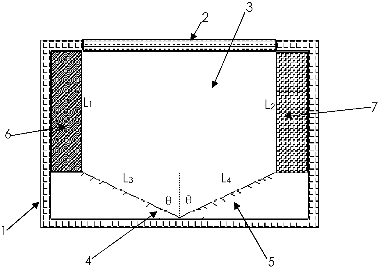
[0025] See figure 1 , the combined solar cell, comprising: a box 1 made of polymer, in which there are two cadmium telluride solar cells 6 and cadmium telluride solar cells 6 and cadmium zinc telluride / monocrystalline silicon laminated solar cells respectively fixed on opposite sides of the inner wall of the box. The battery 7, and two symmetrical reflectors 4 and 5 fixed at an angle θ with the center normal at the bottom of the polymer box, the angle θ is determined by the light-facing surface of the reflector and the normal line at the bottom of the polymer box. The included angle is formed, and the top surface of the box is covered with a glass top cover 2 that can transmit sunlight, thereby forming an incident light area 3 .

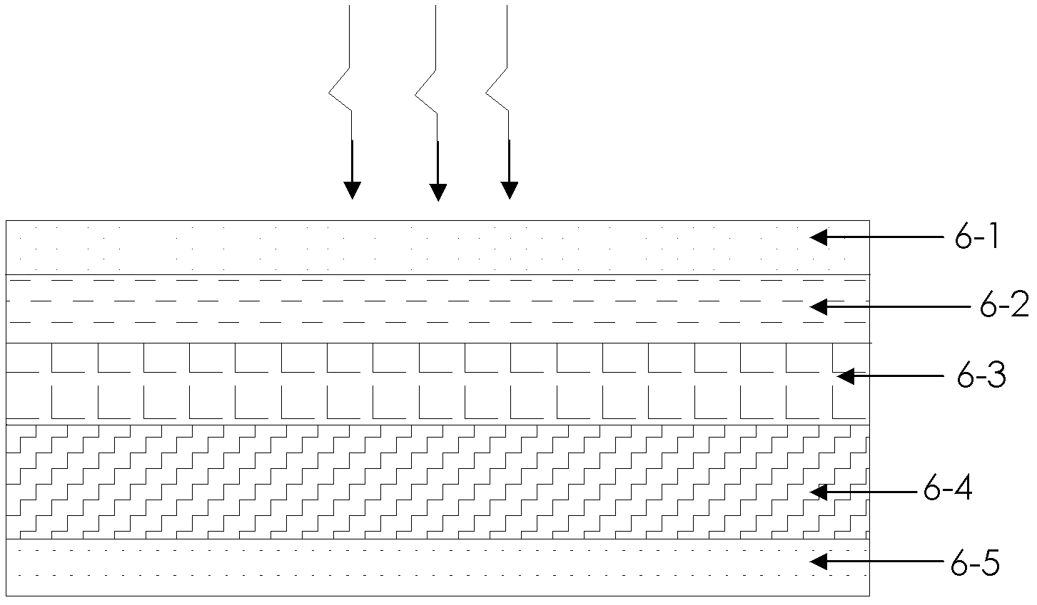
[0026] The structure of cadmium telluride solar cells 6 see image 3 , including: a glass substrate 6-1, on which a transparent conductive oxide front electrode layer 6-2, an n-type CdS window layer 6-3, a p-type cadmium telluride absorbing layer 6-...

Embodiment 2

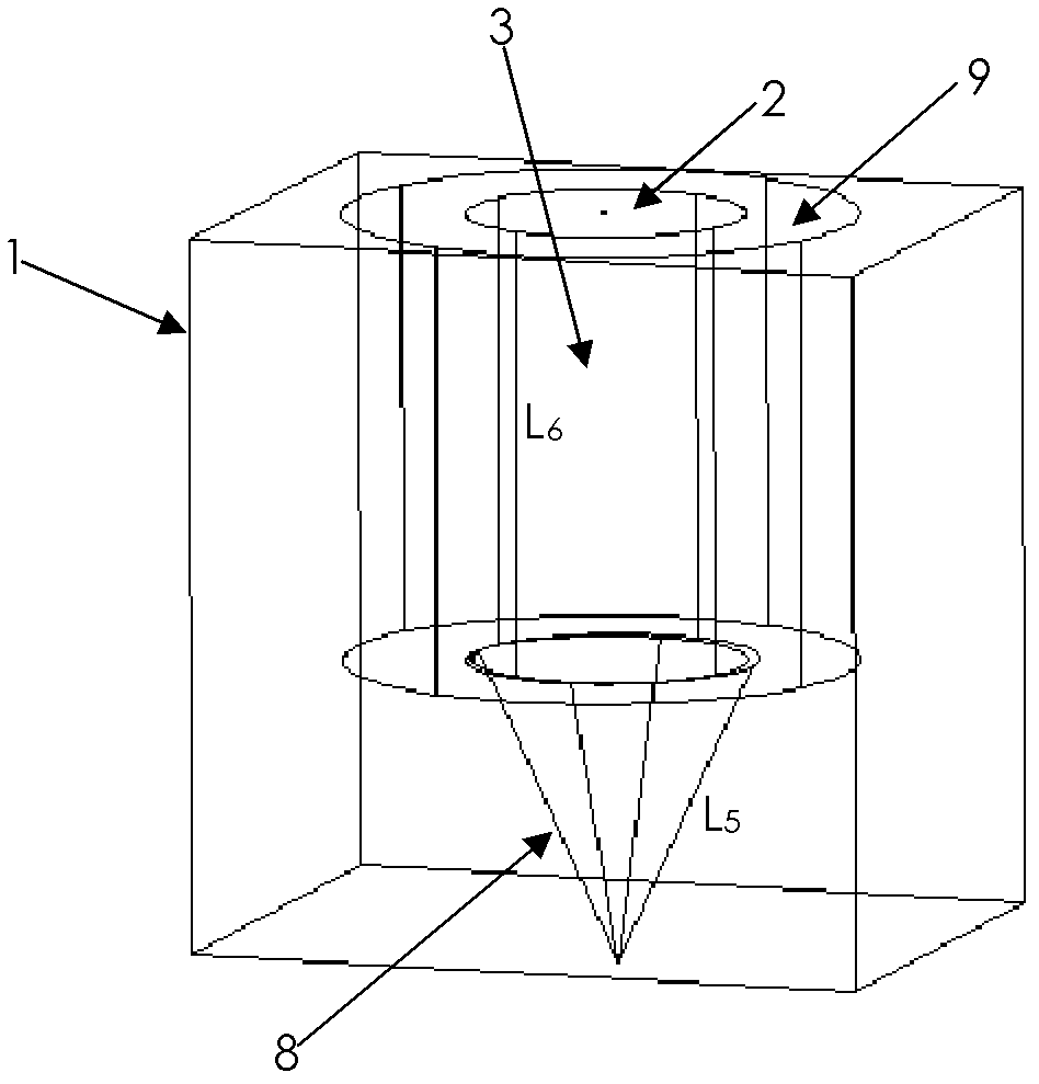
[0032] See figure 2 , the principle of this combined solar cell group is the same as that of Embodiment 1, the difference is that: the two reflectors 4, 5 are replaced by a conical reflector 8, and the solar cells 6, 7 are replaced by a plurality of sub-cells Circular solar cell 9.

[0033] Wherein the light-facing surface of the conical reflector 8 forms an included angle θ with the normal line of the bottom center of the polymer box 1, and θ=60° in this embodiment, so the height of the annular solar cell 9 composed of a plurality of sub-cells It is twice the length of the 8 sides of the conical reflector.

[0034] The sub-cells forming the annular solar cell 9 can be any combination of single-junction solar cells and multi-junction solar cells of any material.

[0035] When the sunlight enters the incident light area 3 through the glass top cover 2, the sunlight is reflected by the light-facing surface of the conical reflector 8 and enters the annular solar cell 9 to gene...


PUM


Abstract

The invention discloses a combined solar battery capable of improving solar energy utilization rate, which comprises a box body formed by polymer, wherein the box body is internally provided with two solar batteries fixed at the two sides of the inner wall of the box body and two reflectors fixed at the bottom part inside the polymer box body at an angle theta, or the box body is internally provided with an annular solar battery composed of a plurality of sub-batteries, and two cone reflectors; the angle theta is formed by an included angle between a light receiving surface of the reflector and a normal line of an inner bottom part of the polymer box body; the top surface of the box body is covered by a glass top cover capable of penetrating sunlight, so that an incident light area is formed. Due to the combined structure of the solar battery, the utilization rate of the solar energy and the photoelectric conversion efficiency of the solar battery are improved, and the batteries are not interfered with each other in the combined structure; the sub-batteries can be combined freely, the combined solar battery is simple in structure, and the problem existing in a traditional laminated battery is effectively avoided.

Description

technical field [0001] The invention relates to a solar cell, in particular to a combined solar cell that can greatly improve the utilization rate of sunlight energy. Background technique [0002] The environmental pollution caused by traditional fossil energy power generation is threatening the earth on which human beings live. Due to the many advantages of using solar energy, it has attracted more and more attention from all over the world. [0003] Because the energy distribution of the solar spectrum is wide, any existing semiconductor material can only absorb photons whose energy is higher than its energy gap value, and the rest of the photons cannot be converted into electrical energy by generating photogenerated carriers. [0004] For this reason, none of the solar cells prepared so far has achieved ideal photoelectric conversion efficiency. In order to improve the photoelectric conversion efficiency of solar cells, people have tried various methods, such as making c...

Claims


Application Information

Patent Timeline
IPC IPC(8): H01L25/10H01L31/052H01L31/0232H02S40/22
CPCY02E10/52Y02E10/50
Inventor 曹鸿褚君浩王善力
Owner 上海太阳能电池研究与发展中心
Why Eureka
Try Eureka