Dielectric lens antenna for high-altitude platform communication system

A technology of dielectric lens antenna and dielectric lens, which is applied in the direction of antenna, antenna array, antenna grounding switch structure connection, etc., can solve the problems of complex manufacturing process, large antenna quality, and large volume, and achieve improved antenna gain, high gain, and low effect of weight

Inactive Publication Date: 2012-07-25
HARBIN INST OF TECH
View PDF2 Cites 10 Cited by
  • Summary
  • Abstract
  • Description
  • Claims
  • Application Information

AI Technical Summary

Problems solved by technology

[0005] The purpose of the present invention is to provide a dielectric lens antenna for high-altitude platform communication system to solve the problems of high-altitude platform communication system antennas with large quality, large volume and complicated manufacturing process

Method used


Image

  • Dielectric lens antenna for high-altitude platform communication system
  • Dielectric lens antenna for high-altitude platform communication system
  • Dielectric lens antenna for high-altitude platform communication system

Examples


specific Embodiment approach 1

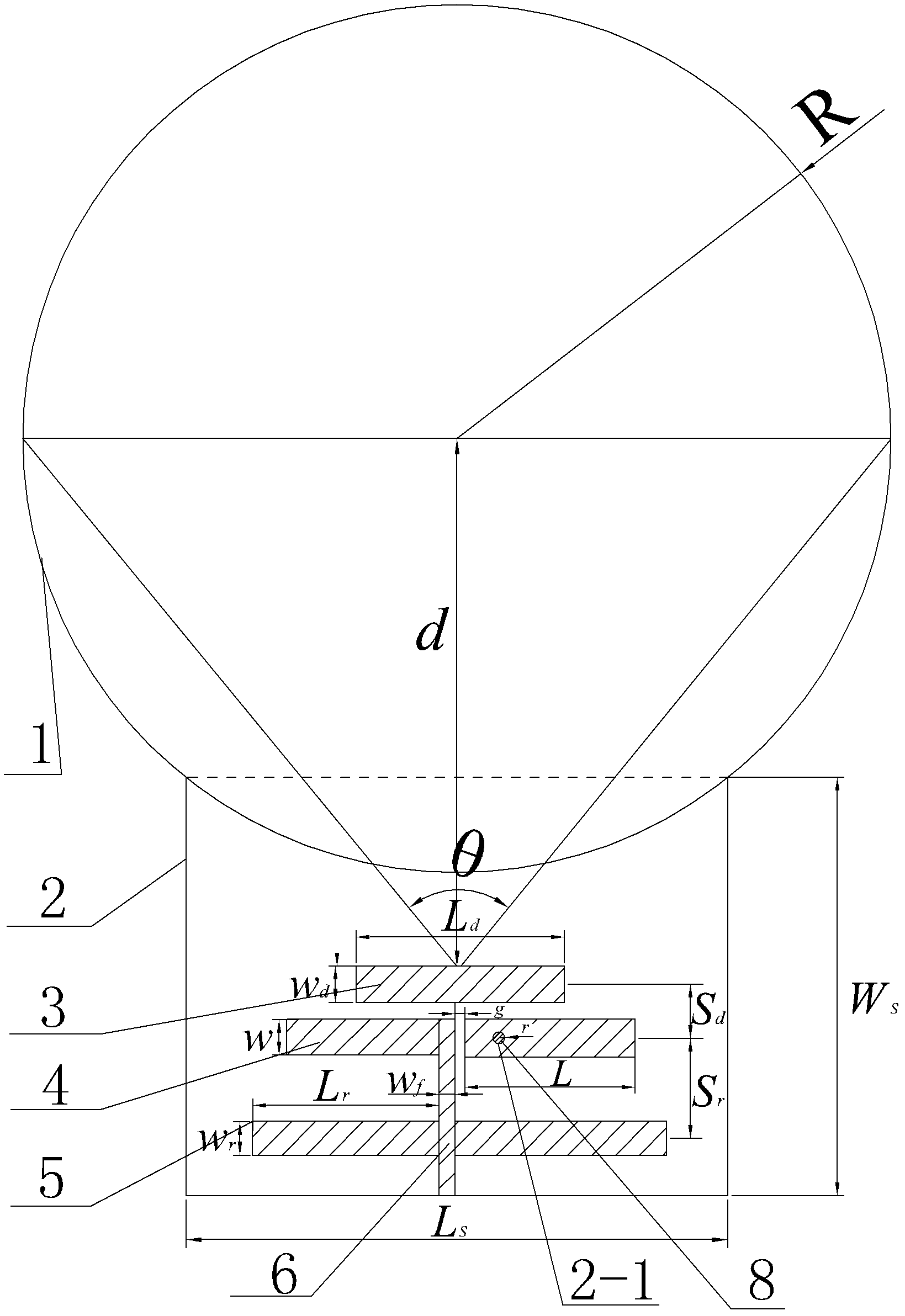
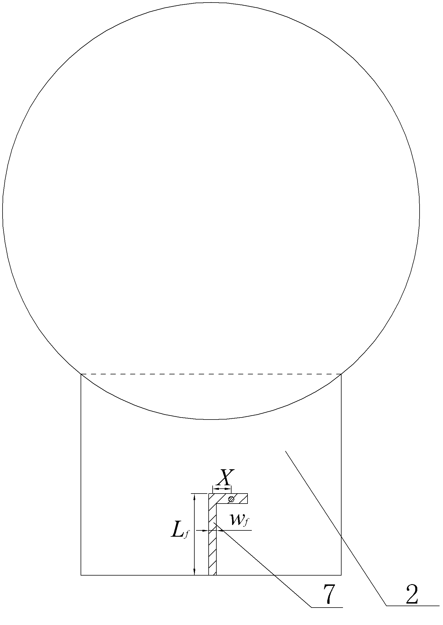
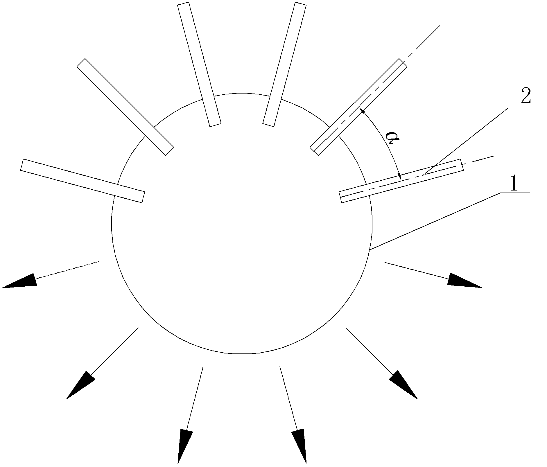
[0010] Specific implementation mode 1: Combination figure 1 To describe this embodiment, the antenna of this embodiment includes a dielectric lens ball 1 and at least one Yagi antenna unit. Each Yagi antenna unit includes a dielectric plate 2, a director 3, two active elements 4, and two reflectors 5, The first balanced microstrip line 6 for feeding and the second balanced microstrip line 7 for feeding, the dielectric plate 2 of the Yagi antenna unit is arranged on the dielectric lens ball 1 along the normal direction of the dielectric lens ball 1 and The two are connected and made into one body. The director 3, the two active oscillators 4, the two reflectors 5, and the first balanced microstrip line 6 for feeding are all set on the front side wall of the dielectric plate 2. The second balanced microstrip line 7 for feeding is L-shaped, the second balanced microstrip line 7 for feeding is arranged on the rear side wall of the dielectric plate 2, and the first balanced microstri...

specific Embodiment approach 2

[0013] Specific implementation manner two: combination figure 1 To illustrate this embodiment, the relative permittivity of the dielectric lens ball 1 of this embodiment is 2.2, the radius R of the dielectric lens ball 1 is 45mm, and the geometric center of the end surface of the director 3 near one end of the dielectric lens ball 1 and the dielectric lens ball 1 The sphere center distance of 1 is d=50mm, and the dielectric lens ball 1 can concentrate electromagnetic energy, which has the functions of improving antenna gain, enhancing antenna directional radiation characteristics and reducing beam width. The other embodiments are the same as the first embodiment.

specific Embodiment approach 3

[0014] Specific implementation mode three: combination figure 1 To describe this embodiment, the dielectric plate 2 of this embodiment is FR-4 epoxy glass cloth laminate, the relative dielectric constant of the dielectric plate 2 is 4.4, the thickness of the dielectric plate 2 is 1.5 mm, and the Yagi antenna unit uses a printed dielectric plate Form, light weight, small volume and easy to process. Other embodiments are the same as the first or second embodiment.


PUM

PropertyMeasurementUnit
Radiusaaaaaaaaaa
Thicknessaaaaaaaaaa
Radius raaaaaaaaaa

Abstract

The invention relates to the field of radio technologies and particularly relates to a dielectric lens antenna for a high-altitude platform communication system. The dielectric lens antenna for the high-altitude platform communication system is used for solving the problems of large mass, big volume and complicated manufacture process of the antenna for the high-altitude platform communication system nowadays. A dielectric lens ball is connected with a dielectric slab of a yagi antenna unit, and the dielectric lens ball and the dielectric slab of the yagi antenna unit are integrally formed; balanced microstrip lines are adopted to feed the antenna; a second balanced microstrip line for feeding is arranged on the rear side wall of the dielectric slab; one end of a first balanced microstrip line for feeding is connected with one of two active oscillators; the other end of the first balanced microstrip line for feeding is simultaneously connected with two reflectors; and a horizontal section of the second balanced microstrip line for feeding is connected with the other one of the two active oscillators through a metal filler. The dielectric lens antenna has the characteristics of wide band, high gain, strong directional radiation property and narrow beam width, and can be applied to prospective high-altitude platform communication systems.

Description

Technical field [0001] The invention relates to the field of radio technology, in particular to a dielectric lens antenna that can be used in a high-altitude platform communication system. Background technique [0002] At present, the wireless communication system has developed in the direction of higher spectrum utilization, larger system capacity and more flexible network coverage. As a new mobile communication method, the high-altitude platform communication system has small free space attenuation and short delay time compared with synchronous satellites; compared with terrestrial cellular systems, its coverage area is large, and its channel fading and transmission power are also low. Can be significantly reduced. At the same time, the high-altitude platform communication system has high flexibility, does not require a complex and large launch base, can also be quickly transferred, and can be used for monitoring and communication in areas where natural disasters occur. [0003...

Claims


Application Information

Patent Timeline
IPC IPC(8): H01Q19/06H01Q19/18H01Q21/00H01Q1/38H01Q1/50H01Q3/24
Inventor 杨明川蔡润南赵琳李明刘晓锋
Owner HARBIN INST OF TECH
Why Eureka
Try Eureka