Urea-solution-based SCR (selective catalytic reduction) flue gas denitration process and device

A technology of solution and urea, which is applied in the separation of dispersed particles, chemical instruments and methods, separation methods, etc., can solve the problems of unsatisfactory pyrolysis effect, complex structure of pyrolysis chamber, and high operating cost, so as to simplify the approval procedures and eliminate Potential safety hazards and environmental risks, and the effect of reducing operating costs

Inactive Publication Date: 2012-08-01
湖南安普诺环保科技有限公司
View PDF5 Cites 23 Cited by
  • Summary
  • Abstract
  • Description
  • Claims
  • Application Information

AI Technical Summary

Problems solved by technology

The disadvantage of this technology is that natural gas or oil is used as the heat source, and the operating cost is high
In the Chinese patent literature, "Direct injection urea method SCR flue gas denitrification process and device" (patent application number: 201010582020.6) is to spray solid urea powder directly into the flue, and use the temperature of the flue gas to pyrolyze the urea into gaseous ammonia. The pyrolysis effect is not ideal; "A urea ammonia production process and system for boil

Method used


Image

  • Urea-solution-based SCR (selective catalytic reduction) flue gas denitration process and device
  • Urea-solution-based SCR (selective catalytic reduction) flue gas denitration process and device
  • Urea-solution-based SCR (selective catalytic reduction) flue gas denitration process and device

Examples


Example Embodiment

[0044] Example 1: SCR flue gas denitration process and device based on urea solution:

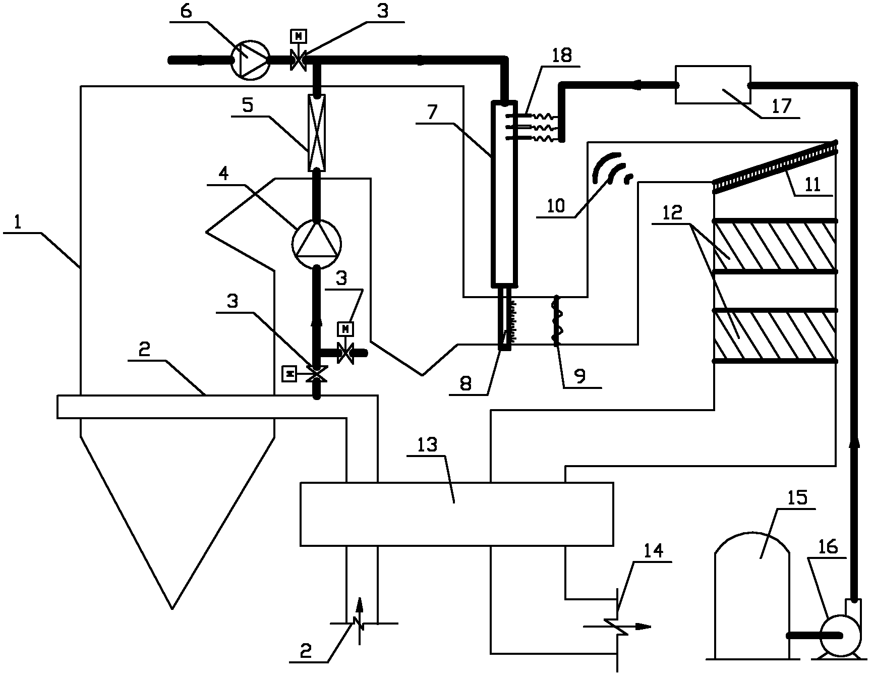
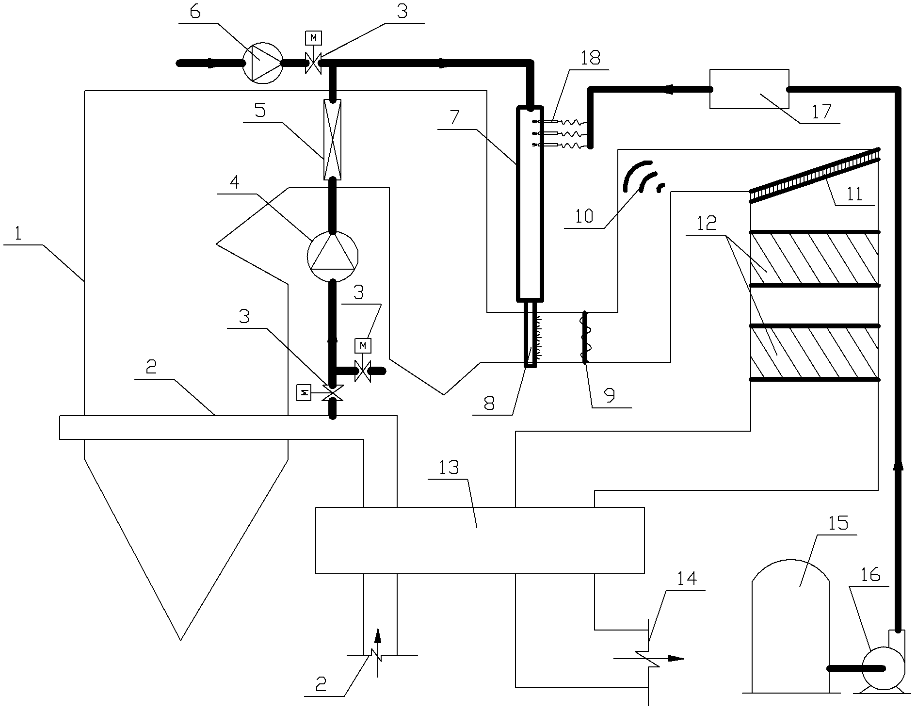
[0045] Such as figure 1 As shown, the pyrolysis air is drawn from the secondary air duct after the air preheater and pressurized by the first fan (the pressure range is 6000-10000Pa, which meets the pressure requirements of the ammonia injection grill). The inside is heated to 350~700℃ by boiler flue gas;

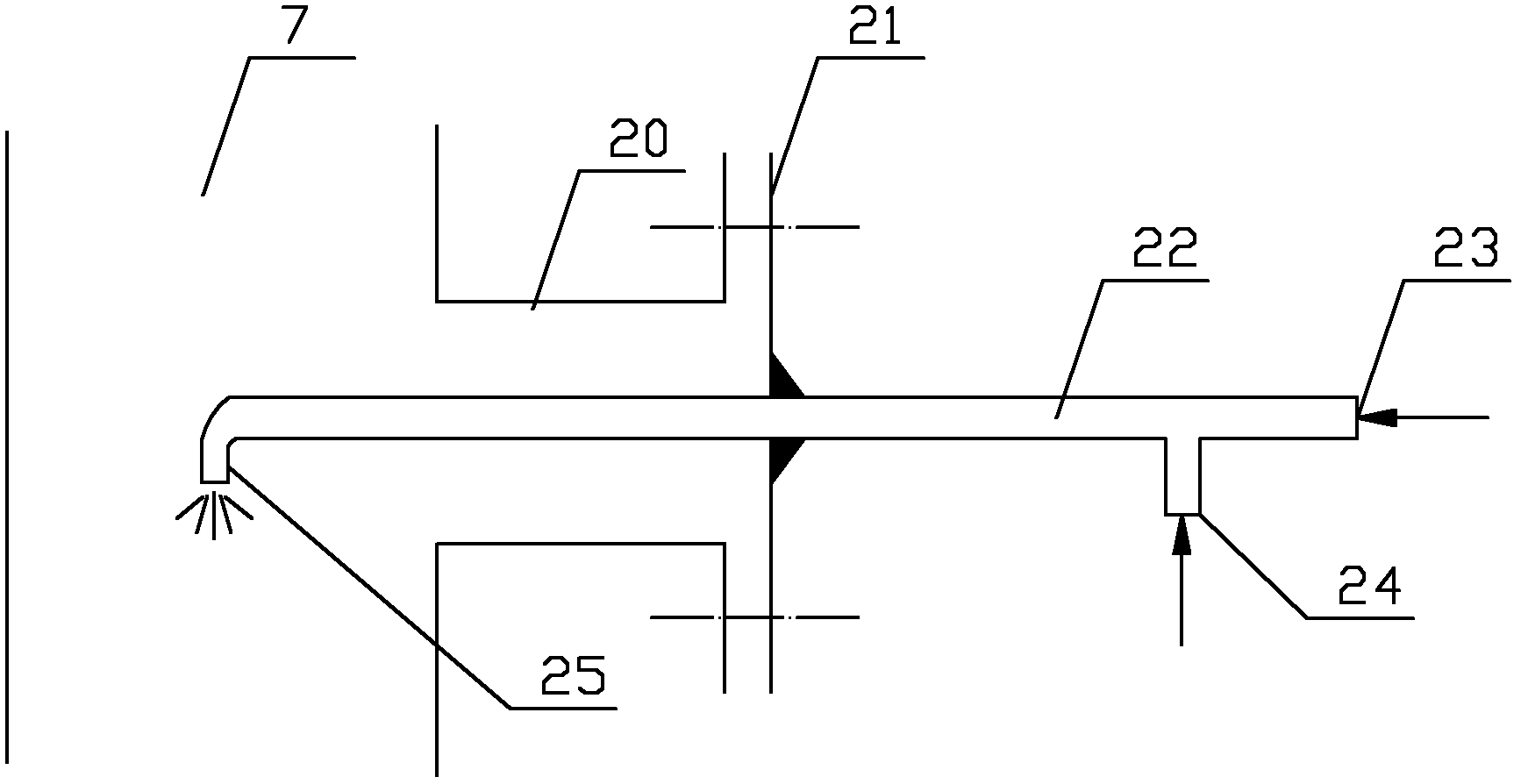
[0046] The prepared 30%-50% urea solution is stored in the storage tank, and the flow is controlled by the urea solution pump pressurization and metering distribution device, and sprayed into the heated pyrolysis air by the atomizing spray gun;

[0047] The atomized urea is rapidly pyrolyzed into gaseous ammonia at high temperature, reaching a safety index of 2 , Complete the denitration process.

[0048] The first fan adopts a frequency conversion fan, which controls the pyrolysis air volume through frequency conversion to match the amount of urea solution sprayed for denitration.

[0049] A nat...

Example Embodiment

[0051] Example 2: Ammonia-based SCR flue gas denitration process and device:

[0052] Such as figure 1 As shown, the pyrolysis air is drawn from outside the furnace, pressurized to 6000-10000Pa by the pyrolysis fan, and heated to 350-700°C by the boiler flue gas in the pyrolysis air heater.

[0053] 15%-20% ammonia solution is stored in the storage tank, and the flow is controlled by the ammonia pump pressurization and metering distribution device, and sprayed into the heated pyrolysis air by the spray gun;

[0054] The atomized ammonia quickly vaporizes into gaseous ammonia at high temperature, and is evenly sprayed into the inlet flue of the denitration reactor through the ammonia spraying grid, and is fully mixed with the flue gas through the mixer, and enters the denitration reaction evenly after passing through the deflector and rectifier By the catalyst, the NO in the flue gas is reduced to N 2 , Complete the denitration process.


PUM


Abstract

The invention discloses a urea-solution-based SCR (selective catalytic reduction) flue gas denitration process and device. According the process, pyrolysis air is pumped from the outside or a second air channel of a boiler, then is pressurized by a first fan and heated to 350-700 DEG C by a pyrolysis air heater arranged in a boiler hearth or a tail air channel, and the heated pyrolysis air enters a pyrolysis reaction air channel together with fresh air; urea solution is sprayed into the pyrolysis air channel by an atomizing spray gun and the atomized urea solution is pyrolyzed into ammonia gas in the pyrolysis air channel; and after being discharged out of the pyrolysis air channel, the ammonia gas is sprayed into boil flue gas via ammonia spraying grilles to participate in the SCR reaction in an SCR reactor arranged in a tail flue of the boiler. the urea-solution-based SCR flue gas denitration process and device have the advantages of high safety, simple structure and easiness in implementation.

Description

technical field [0001] The invention belongs to the technical field of flue gas nitrogen oxide emission reduction (denitration) and relates to a urea solution-based SCR flue gas denitrification process and device. Background technique [0002] Flue gas selective catalytic reduction (SCR) denitrification process is currently the main technology for flue gas denitrification. The SCR process is a selective reduction reaction between the amino reducing agent and the NO in the flue gas under the action of a catalyst to generate N 2 and water, thereby eliminating pollution. In order to ensure the effect of mixing and reaction, the ammonia reducing agent is required to be evenly sprayed into the flue in gaseous form through the ammonia spraying grid, so the reducing agent is usually liquid ammonia that is easy to evaporate. However, liquid ammonia is a dangerous chemical, and its transportation and storage are strictly restricted, which brings more inconvenience to the initial co...

Claims


Application Information

Patent Timeline
IPC IPC(8): B01D53/56B01D53/90
Inventor 彭峻
Owner 湖南安普诺环保科技有限公司
Why Eureka
Try Eureka