Industrial furnace for non-ferrous metal smelting

A non-ferrous metal, industrial furnace technology, applied in furnaces, furnace components, preheating costs, etc., to avoid a large amount of loss, avoid damage, and reduce energy consumption

Inactive Publication Date: 2012-08-01
MEISHAN ZHONGNENG ALUMINUM
View PDF6 Cites 12 Cited by
  • Summary
  • Abstract
  • Description
  • Claims
  • Application Information

AI Technical Summary

Problems solved by technology

[0009] The technical problem to be solved by the present invention is an industrial furnace for smelting non-ferrous metals with high efficiency, low energy consumption, low aluminum loss and little heat pollution

Method used


Image

  • Industrial furnace for non-ferrous metal smelting
  • Industrial furnace for non-ferrous metal smelting
  • Industrial furnace for non-ferrous metal smelting

Examples


Embodiment 1

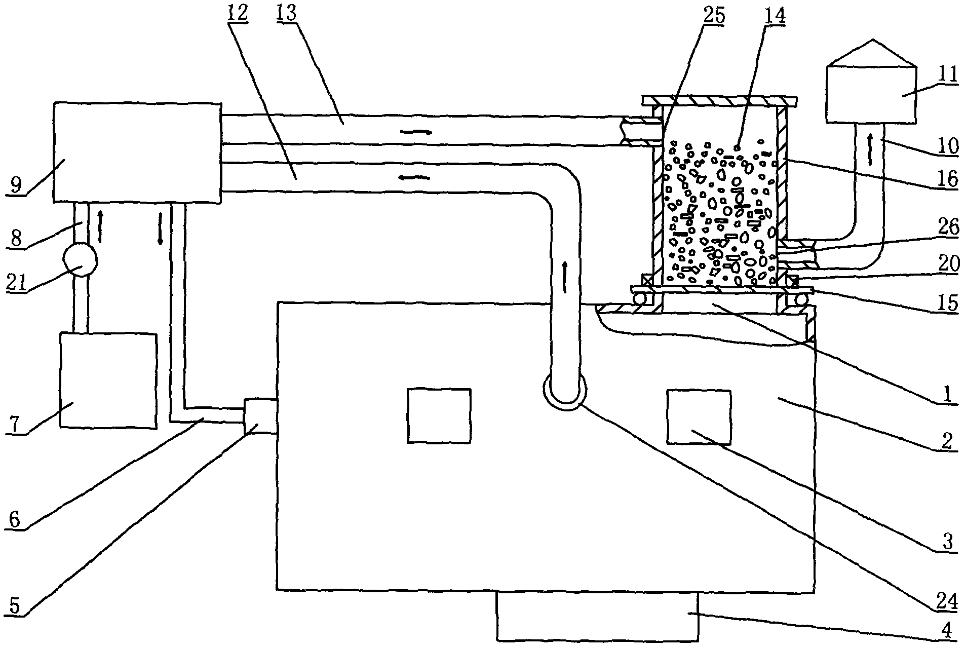
[0038] Embodiment one: if figure 1 As shown, the present invention mainly consists of a furnace 2, a vertical feed cylinder 16 connected to the furnace feed port 1, a fuel device 5 connected to the left end wall of the furnace 2, a mixer 4 positioned at the bottom of the furnace 2, and a furnace mounted on the furnace. 2 outside the heat exchange system; the furnace feed inlet 1 is located at the right end of the furnace top of the furnace 2, and two furnace doors 3 slightly higher than the liquid level of the charge 14 in the furnace are formed on the front side wall of the furnace 2. A furnace gas outlet 24 is formed on the front side wall in the middle of the door 3; Gas outlet 26; the heat exchange system is mainly composed of heat exchanger 9, fan 7, vertical feed cylinder 16, low temperature air pipeline 8, high temperature air pipeline 6, first stage furnace gas pipeline 12, second stage The furnace gas pipeline 13 is formed, the low-temperature air pipeline 8 is conn...

Embodiment 2

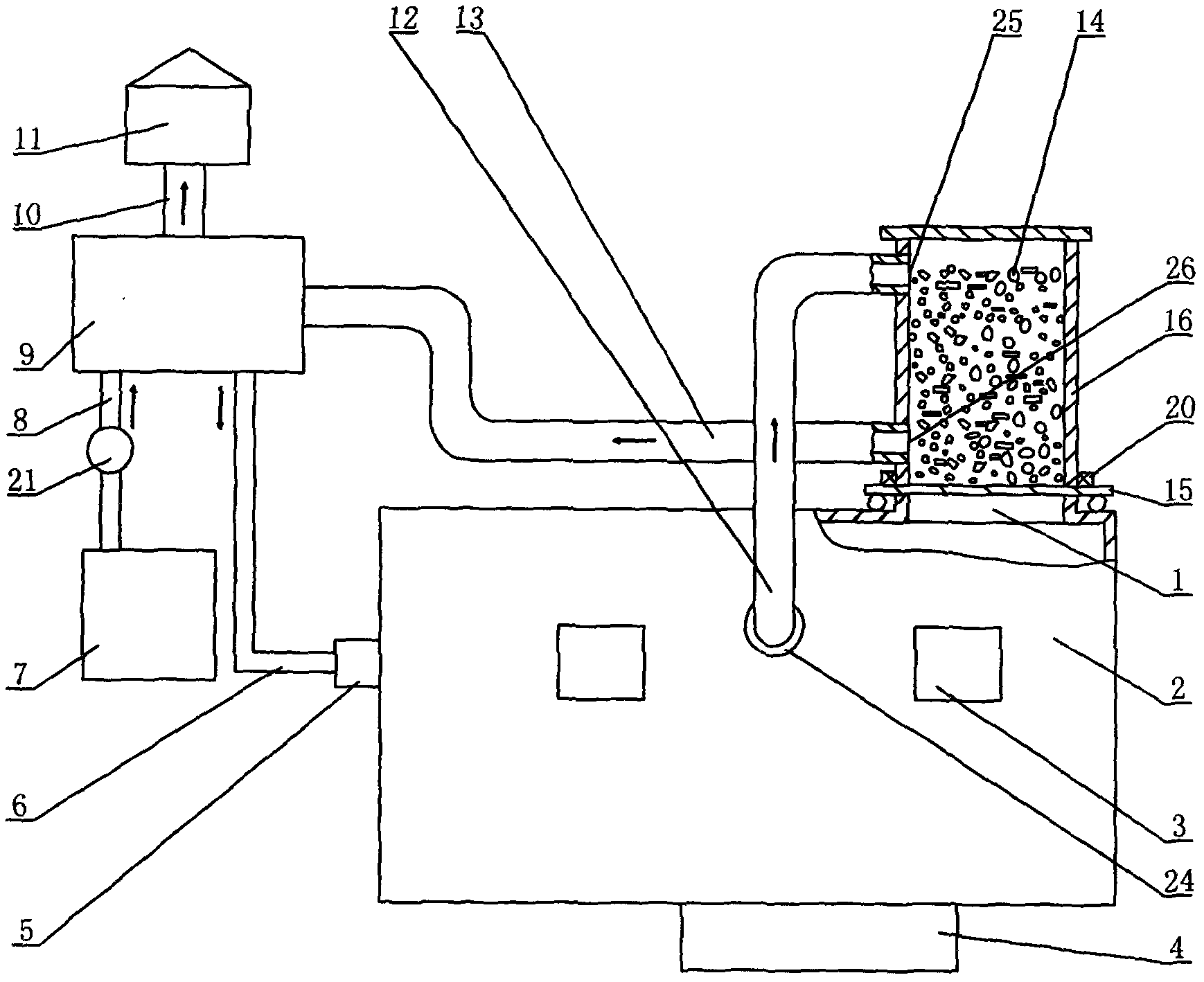
[0042] Embodiment two: if figure 2 As shown, the present invention mainly consists of a furnace 2, a vertical feed cylinder 16 connected to the furnace feed port 1, a fuel device 5 connected to the left end wall of the furnace 2, a mixer 4 positioned at the bottom of the furnace 2, and a furnace mounted on the furnace. 2 outside the heat exchange system; the furnace feed inlet 1 is located at the right end of the furnace top of the furnace 2, and two furnace doors 3 slightly higher than the liquid level of the charge 14 in the furnace are formed on the front side wall of the furnace 2. A furnace gas outlet 24 is formed on the front side wall in the middle of the door 3; Gas outlet 26; the heat exchange system is mainly composed of heat exchanger 9, fan 7, vertical feed cylinder 16, low temperature air pipeline 8, high temperature air pipeline 6, first stage furnace gas pipeline 12, second stage The furnace gas pipeline 13 is formed, the low-temperature air pipeline 8 is conn...

Embodiment 3

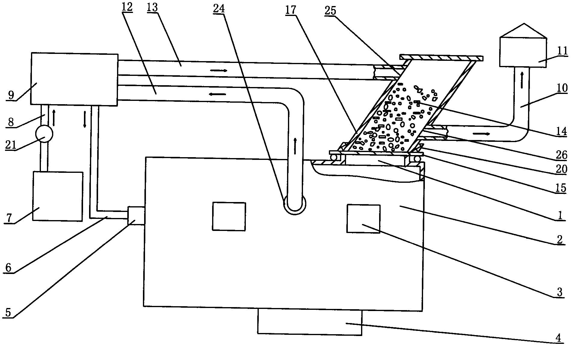
[0046] Embodiment three: as image 3 As shown, the present invention mainly consists of a furnace 2, an oblique feeding cylinder 17 connected to the furnace feed port 1, a fuel device 5 connected to the left end wall of the furnace 2, a mixer 4 positioned at the bottom of the furnace 2, installed on the The heat exchange system outside the furnace 2 is composed of; the furnace feed inlet 1 is located at the right end of the furnace roof of the furnace 2, and two furnace doors 3 slightly higher than the liquid level of the charge 14 in the furnace are formed on the front side wall of the furnace 2. Furnace furnace gas outlet 24 is shaped on the front side wall in the middle of furnace door 3; Barrel furnace gas outlet 26; the heat exchange system is mainly composed of heat exchanger 9, fan 7, oblique feeding cylinder 17, low temperature air pipeline 8, high temperature air pipeline 6, first stage furnace gas pipeline 12 , The second-stage furnace gas pipeline 13 is formed, the...


PUM


Abstract

The invention discloses an industrial furnace for non-ferrous metal smelting. The industrial furnace comprises a hearth (2), a feed tube, a combustor (5) and a heat exchanger (9), wherein a low-temperature air pipeline (8) is connected between the heat exchanger (9) and a fan (7), a high-temperature air pipeline (6) is connected between the heat exchanger (9) and the combustor (5), a hearth furnace gas outlet (24) is formed on the hearth (2), the feed tube serves as one part of a heat exchange system, and a furnace gas pipeline connects the hearth furnace gas outlet (24), the heat exchanger (9) and the feed tube into a whole. According to the invention, the feed tube can utilize excess heat of waste furnace gas to preheat furnace materials (14) to be melted, and loading process is performed in a closed space, thereby preventing a great deal of heat in the furnace from being lost and greatly reducing the temperature of the waste furnace gas discharged into the atmosphere, therefore, the preheated furnace materials (14) can be quickly melted in the hearth (2) so as to achieve the aims of high efficiency, low energy consumption and low aluminum loss.

Description

technical field [0001] The invention relates to a furnace mainly used for smelting metals, in particular to an industrial furnace for smelting non-ferrous metals which utilizes waste furnace gas for multiple heat exchanges and uses waste aluminum alloy as the main charge. Background technique [0002] At present, the annual utilization of scrap nonferrous metals in my country is very large, and the related industries of scrap nonferrous metals occupy an important position in the national economy. We can use aluminum alloy, one of the most commonly used nonferrous metals, as an example to illustrate. [0003] Over the years, with the rapid development of the national economy and the rapid improvement of people's living standards, the demand for scrap aluminum alloys in my country has increased rapidly, and has reached an annual consumption level of more than 8 million tons. In addition to being affected by non-processing factors such as scrap recycling prices, the cost of scr...

Claims


Application Information

Patent Timeline
Patent Type & Authority Applications(China)
IPC IPC(8): F27B3/00F27B3/10F27B3/26F27B3/18F27D13/00F27D17/00
Inventor 冯跃平冯笑冯与佳
Owner MEISHAN ZHONGNENG ALUMINUM
Why Eureka
Try Eureka